1. Introduction
For the past few decades, generation of Laser Induced Periodic Surface Structures (LIPSS) on various materials is studied extensively due to its vast applications in optoelectronics, photonics, plasmonics, biomaterials and thermal radiation sources [
1,
2,
3,
4,
5]. LIPSS can be generated on any kind of solid material by irradiating the material surface with any linearly polarized laser light having a fluence near the ablation threshold [
6]. Ultrashort pulsed lasers are efficient in generating LIPSS on nearly all kind of solid materials [
2,
7]. It can create LIPSS on metals, semiconductors and even dielectrics [
8,
9,
10]. Based on the spatial periodicity of the induced structures, LIPSS can be categorized into two main divisions: those with Low Spatial Frequency and those with High Spatial Frequency. Low spatial frequency LIPSS (LSFL) are having a periodicity close to the laser wavelength λ (Λ
LSFL > λ/2) and high spatial frequency LIPSS are having a periodicity less than half of laser wavelength λ (Λ
HSFL < λ/2)[
11]. It is generally agreed that the formation of LSFL is caused by the interference of the incident laser beam with a surface electromagnetic wave (SEW) [
10,
12] and/or surface plasmon polaritons (SPPs) [
7,
13,
14].
The formation of High Spatial Frequency LIPSS (HSFL) has been debated, with various theories suggesting self-organization [
12], nanoplasmonic excitations [
15,
16], interference and second-harmonic generation [
17,
18,
19], etc. Linearly polarized femtosecond laser writing with high pulse energies and long pulse duration results in formation of self-organized periodic nanostructures. Reported structures in fused silica are of orientation perpendicular to electric field vector. The existence of a steady average period irrespective of target motion suggests a self-replication mechanism behind formation of nanogratings [
20]. According to nanoplasmonics, as pulse fluence reaches the ablation threshold, a pair of peripheral nanoplasma zones are created leading to local intensity enhancement, as in the case of the central nanoplasma zone. This evolution of the onset of side-maxima and the corresponding “self-seeding” from the incubation effect led to the formation of the periodic structure [
15]. The interference effect is also a significant mechanism that predicts HSFL formation. Multi-photon absorption produces electrically unstable surfaces that result in intense emission of electrons and positive ions, hence forms surface plasma and plasmons [
21]. Surface plasmons are excited and interfere with absorbed laser field. Then, intensity is strongly reprofiled and shows periodic patterns that locally enhances the field and ablation which leads to the formation of periodic structures [
22]. As the ripples grow, the grating assisted surface plasmon-laser coupling plays an important role in further process [
23]. Besides these, compound materials are anticipated undergoing modifications during multi-pulse irradiation. Thus, near surface region of these materials might facilitate harmonic generation and explain an orientation insensitivity. There is an approximate correspondence that some of HSFL periods are laser second harmonic wavelengths [
24].
The spatial periodicity of the LIPSS under the irradiation with femtosecond laser pulses has been found to depend upon various experimental parameters such as incident laser wavelength [
25,
26], laser fluence [
27], polarization [
28], number of pulses [
13], the ambient environment [
29,
30] and also the properties of the material [
31]. Taher et al. reported the variation in the spatial periodicity of LSFL from λ/1.7 to λ/4.7 and HSFL from λ/8 to λ/30 upon increasing the wavelength from 400 nm to 2200 nm [
25]. Shi et al. reported that the laser fluence plays a vital role in the formation of LIPSS and they show that lower fluence corresponds to the generation of HSFL while higher fluence corresponds to the generation of LSFL [
27]. Bonse et al. showed that at a fixed peak fluence, the mean spatial periodicity of LIPSS generated on a single crystalline silicon is decreased monotonously between 770 nm and 560 nm as on varying the number of shots from 1 to 1000 [
13]. Gregorčič et al. reported that the rotation in the polarization of the irradiated picosecond laser pulse resulted in corresponding rotation in the ripples produced on a steel substrate [
28]. Gräf et al. reported that the threshold fluence for the formation of low-spatial frequency LIPSS (LSFL) on fused silica is reduced and the periodicity of LSFL is increased up on increasing the substrate temperature [
29]. Nürnberger et al. reported that the orientation of LIPSS generated is influenced by the grain structure as well as the crystal orientation of each individual grain of the substrate [
31].
The superior mechanical, physical, and chemical characteristics of materials such as borosilicate glass, soda-lime glass, and fused silica make them an ideal choice for applications in optics, microfluidics, photovoltaics, and biomaterials [
32]. Femtosecond laser assisted processing has become a powerful and efficient way for nano/microfabrication of glass surfaces [
33]. There are many works that have reported the formation of LIPSS on glass [
10,
34]. But most of them are limited to single spot or a line segment. The lack of investigations is due to difficulties with LIPSS generation on glasses, which are mostly brought on by their amorphous chemical structure and comparatively high band gap energy when compared to metals and semiconductors. This high band gap energy causes ultrashort laser pulses to undergo a non-linear, multi-photon absorption. These properties make glasses more vulnerable to changes in laser irradiation, defects, and incubation. Also, only few works are reported on generating LIPSS on borosilicate glass when compared to that of other types of glass. The LSFL are typically formed for higher laser fluences or number of pulses on silica-based glasses [
10,
34,
35,
36]. The HSFL was observed only in few glasses[
10,
37]. Höhm et al. has reported the generation of high-spatial-frequency LIPSS with spatial periods between 170 nm and 450 nm and orientation perpendicular to the polarization on silica using femtosecond laser with central wavelength 800 nm and pulse duration 150 fs [
10]. This work mainly aims to explore the potential for creating high spatial frequency LIPSS (HSFL) over a large surface area of borosilicate glass. Additionally, we studied the optical and wetting characteristics of the induced structures.
2. Materials and Methods
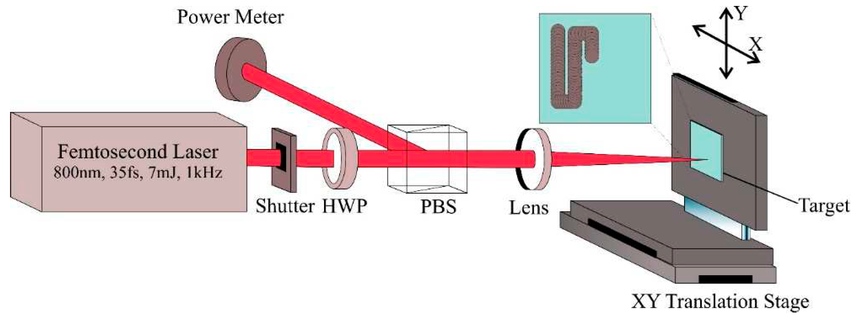
Surface texturing of Borosilicate glass was done by irradiating with a Ti-Sapphire femtosecond laser system (Coherent Astrella) which emits a linearly polarized laser pulse of energy 7 mJ and a pulse duration of 35 fs. The laser has a central wavelength of 800 nm and a repetition rate of 1 kHz. An electromechanical shutter is used to control the laser dose on the target. A combination of half-wave plate and polarizing beam splitter was used in the optical path for precise control of laser energy and to choose a particular polarization. The beam was focused using a lens of 300 mm focal length onto the surface of the sample at normal incidence. Optically flat Borosilicate glass of thickness 130 μm is used as the substrate which has been mounted on a motorized XY translation stage for line-by-line scanning. All the texturing processes were carried out in atmospheric conditions and the complete schematic is shown in
Figure 1.
The ablation threshold for different number of shots was determined using the D square method or Liu’s method [
38] and the incubation parameter was determined using the accumulation model by Jee et.al [
39]. For this the surface of the substrate is irradiated with different number of shots ranging from 10 to 100 with different pulse energies ranging from 20 μJ to 100 μJ. The generation of LIPSS upon the variation in pulse number and pulse energy was studied by analyzing the topography of the crater formed on the substrate. Also, the generation of LIPSS over a single line was investigated for scanning orientation parallel and perpendicular to the laser beam polarization by varying the scanning speed. The large-area structuring was done by line-by-line scanning over an area of 10 x10 mm
2 with a peak laser fluence of 2.71 J/cm
2 at a scanning speed of 2000 μm/s along a scanning orientation parallel to the polarization axis.
The topographical analysis of the processed substrate surface was done using a Field Emission Scanning Electron Microscope (Carl Zeiss Sigma VP) and Atomic Force Microscope (Keysight 5500AM). Also, the reflectance and transmittance of the processed substrate surface was done using a UV-Visible-near IR spectrophotometer (Jasco V770). The wetting properties of the processed substrate surface was analyzed using a contact angle goniometer (Rame-hart 290-U1).
3. Results and Discussion
3.1. Ablation Threshold Estimation
The ablation threshold of borosilicate glass was estimated using D squared method introduced by Liu [
38]. According to this method, the diameter of the ablation crater is related to the applied laser fluence through the equation,
where D is the crater diameter, ω
o is the beam radius at 1/e
2 the peak value, E is the laser pulse energy, F is the peak fluence of the incident laser pulse and F
th is threshold fluence. For a gaussian laser profile, threshold peak fluence (F
th) can be related to the threhold pulse energy(E
th) by,
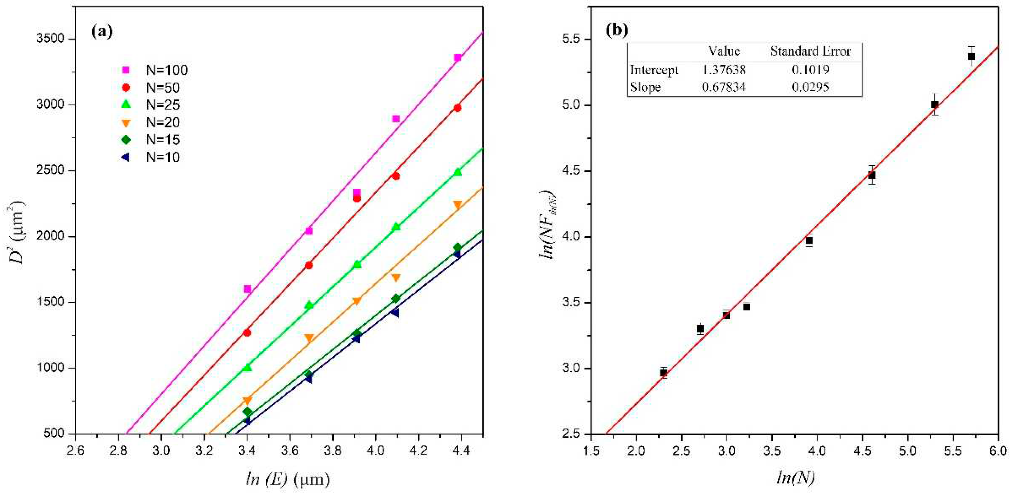
Diameter of the crater was estimated accurately from the FESEM images. The beam waist was estimated by plotting the square of the crater diameters (D
2) versus the logarithm of the laser pulse energy (E) for different numbers of irradiated laser pulses as shown in
Figure 2a and the value was found to be 27.12±1.95 μm. The peak fluence versus crater diameter plot for different numbers of overlapping pulses is shown in
Figure 2a. The threshold fluence (F
th) for different number of shots was estimated by extrapolating the least square fit.
From
Figure 2a it is found that the ablation threshold decreased from 1.94 J/cm
2 to 0.87 J/cm
2 when the number of laser pulses increased from 10 to 100 shots, which is caused by the material-dependent "incubation effect” [
40,
41,
42]. The incubation effect is attributed to be due to the generation of surface defects by the interaction of multiple laser pulses with fluences lower than the single-shot ablation threshold. These defects can cause ablation at lower threshold levels, as they alter the mechanical and/or chemical properties of the material[
43,
44]. In the case of femtosecond laser ablation, the most likely hypothesis on the origin of incubation is an increment in surface roughness after multi-shot irradiation, due to ripple formation or accumulation of surface defects. The initial laser pulses cause imperfections in the material, allowing subsequent pulses to be absorbed better and thus improving the ablation and material removal process [
45].
The observed accumulation behavior has been explained in terms of an incubation model by Jee et al. [
39]. The ablation threshold fluence
Fth(N) for
N laser shots is related to the single-shot ablation threshold fluence through the power law:
The incubation coefficient S serves to quantify the degree of accumulation which is present in a material. When S equals 1, the effect of accumulation is null. It can be understood from Eq. (3) that the logarithm of the product
N Fth(N) is proportional to
ln N with the proportionality constant
S. From
Figure 2b the slope of the plot, which is the incubation parameter, was found to be
S = 0.68±0.03 and using the Eq. (3) the ablation threshold for single shot was found to be
Fth(1) = 3.87±0.26 J/cm
2. Gräf et al. reported an ablation threshold of 4.1 J/cm
2 for borosilicate glass upon irradiating with 5 shots of femtosecond laser pulse having pulse duration 300 fs, a central wavelength 1025 nm [
36].
3.2. Single Spot Analysis
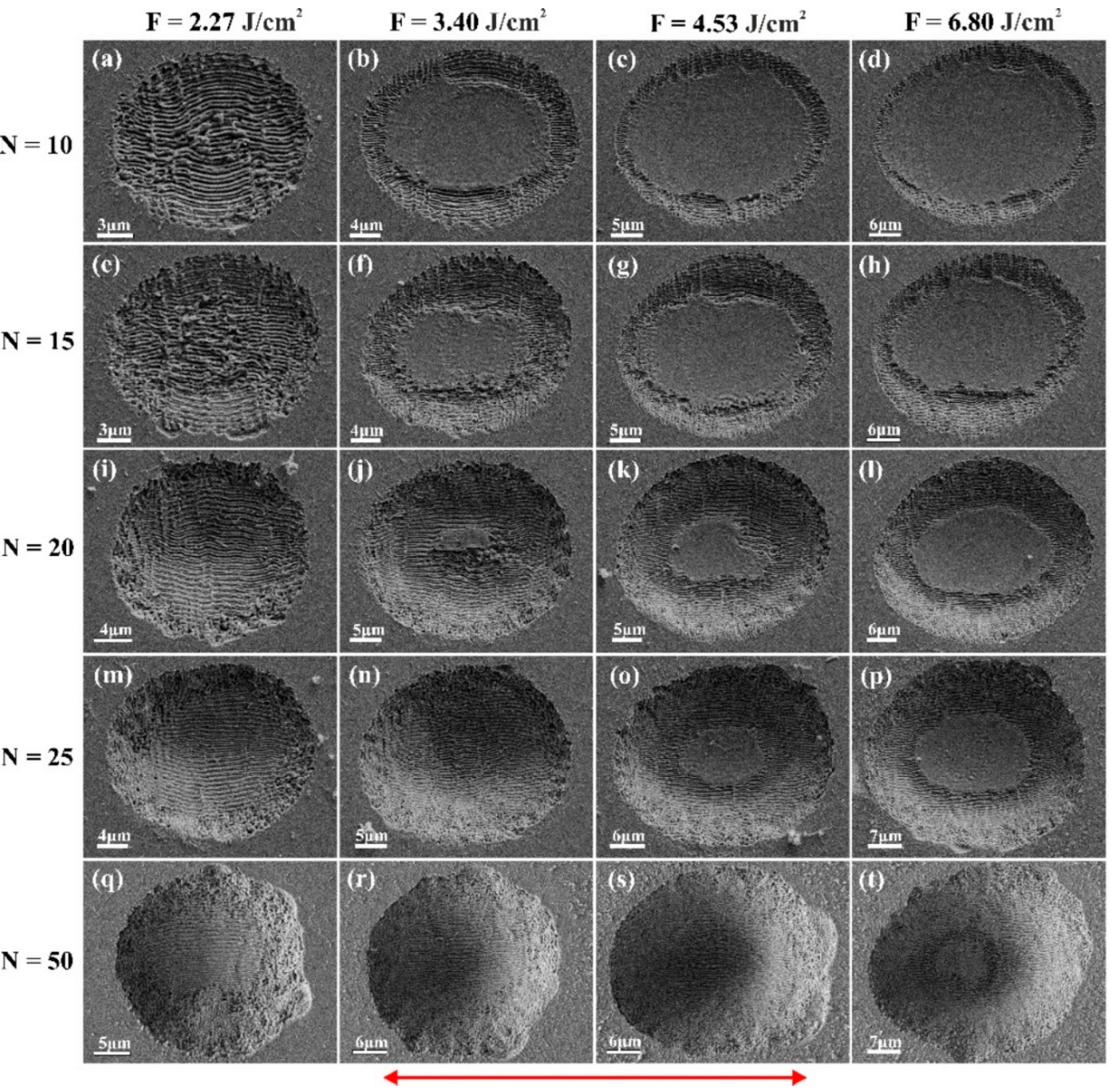
The evolution of LIPSS on borosilicate glass at a single spot is analyzed by varying the number of shots and the fluence of the incident laser light. The FESEM image of the crater formed on borosilicate glass irradiated with different number of linearly polarized femtosecond laser pulses at different peak fluences is shown in
Figure 3. The laser peak fluence is varied from 2.27 J/cm
2 to 6.80 J/cm
2 and the number of pulses varied from 10 to 50. It is observed that Laser Induced Periodic Surface Structures (LIPSS) having an orientation parallel to the electric field vector is formed on the borosilicate glass surface when it is irradiated with femtosecond laser pulses in the investigated parametric range. When the number of irradiated laser pulses is increased by keeping the laser peak fluence at a fixed value, say
F = 2.27 J/cm
2 (
Figure 3a,e,i,m,q), the peripheral region of the crater was found to be losing its periodic nature leading to the formation of random nano/microstructures over the outer region of crater. Also, on increasing the irradiated laser peak fluence for a fixed number of shots, say 10 shots (
Figure 3a‒d), melt formation was observed at the central region of the crater where the intensity is maximum for a gaussian beam profile and LIPSS formation is limited to the peripheral region of the crater. Gräf et al. and Ben-Yakar et al. reported the melt formation at the center of the crater of borosilicate glass at higher laser peak fluences [
36,
46].
When a substrate is irradiated with ultrashort laser pulse, a major portion of the absorbed energy by the substrate will be utilized by the plasma to expand into its surrounding gas [
47]. A small portion of it remains in the substrate as thermal energy. This thermal energy deposited in the bulk of the glass forms a transient shallow area of molten glass beneath the expanding plasma [
48]. During the lifespan of the melt, the forces (thermocapillary forces and the forces by the plasma pressure) acting on the molten material drive the liquid to the crater's edges, and when the melt resolidifies, they produce a raised rim around the ablated crater [
46]. According to Gräf et al. these melt formations are unaffected by inter-pulse effect of heat accumulation due to the sequential irradiation of laser pulses [
36]. But in our studies, we found that the size of these melt formations is reduced and even gets totally removed as on increasing the number of shots (
Figure 3n,r,s).
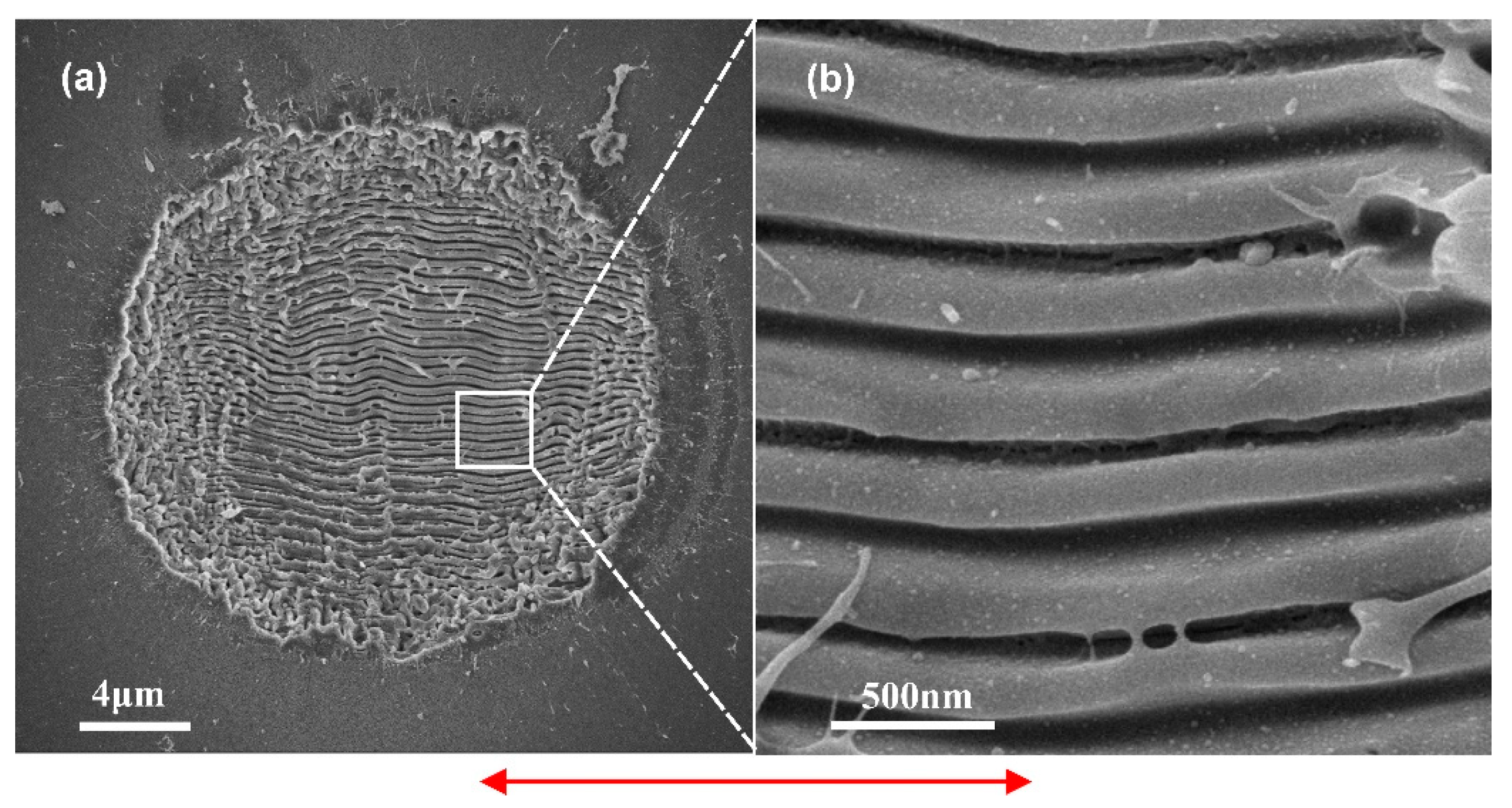
Upon observing the topography of a crater formed by irradiating the substrate with 20 laser shots having a fluence of 2.27 J/cm
2 (
Figure 4), it was found that the LIPSS formed on the surface are having a periodicity 320±60 nm. These kind of LIPSS having periodicity less than half of the wavelength of the laser are categorized to be high spatial frequency LIPSS(HSFL) [
11].
3.3. Large Area HSFL
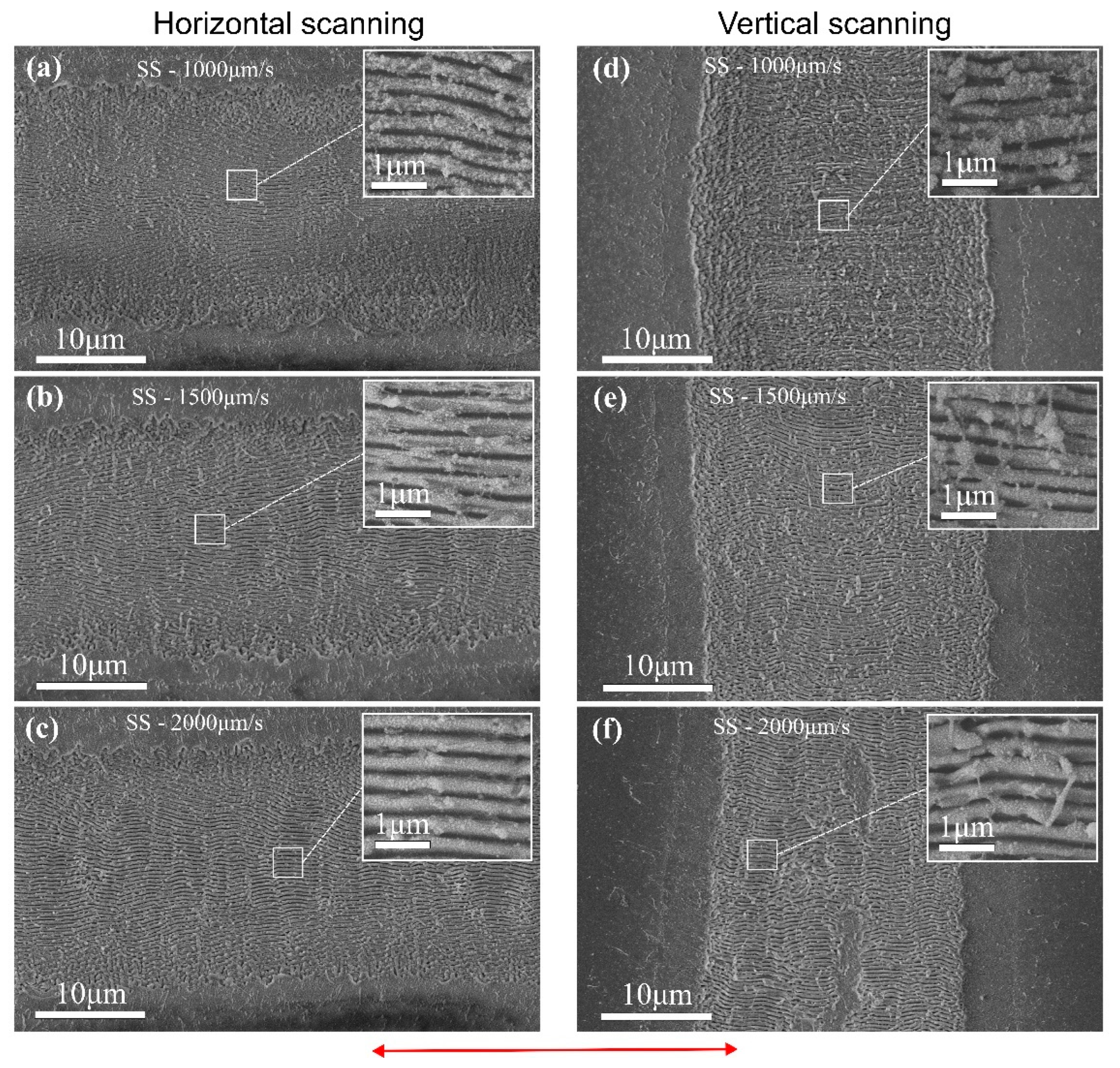
Based on the single-spot trials, further investigations were aimed to realize large areas homogenously structured with high spatial frequency LIPSS (HSFL). For the generation of a large area with HSFL, the LIPSS formation behavior in a single scan line along parallel and perpendicular to the axis of the electric field vector is studied. For this the surface of the substrate is irradiated in a scanning manner with a laser peak fluence of 2.71 J/cm2 at different scanning speeds, say 1000 μm/s, 1500 μm/s and 2000 μm/s, along the horizontal and vertical scanning directions.
The HSFL generated at different scanning speeds are found to be having almost same periodicity. At lower scan speed of 1000 μm/s (
Figure 5a,d) the redeposition of nanoparticles is high when compared to that of higher scan speeds. When comparing the structures according to the scanning orientation, scanning along the vertical axis (⊥ to the direction of the electric filed vector) is found to be having more redeposition than scanning along horizontal direction (∥ to the direction of the electric filed vector). Also, at a higher scanning speed of 2000 μm/s along vertical direction (
Figure 5f) the melt formations are observed. So, it is clear that the orientation of the scan axis with the laser beam polarization significantly affects the uniformity of large-area processing, with redeposition and melt formation being higher when the scan axis is perpendicular to the laser beam polarization.
The large area HSFL on borosilicate glass is generated by line-by-line scanning of the glass surface at a scan speed of 2000 μm/s along the horizontal direction with a laser peak fluence of 2.71 J/cm
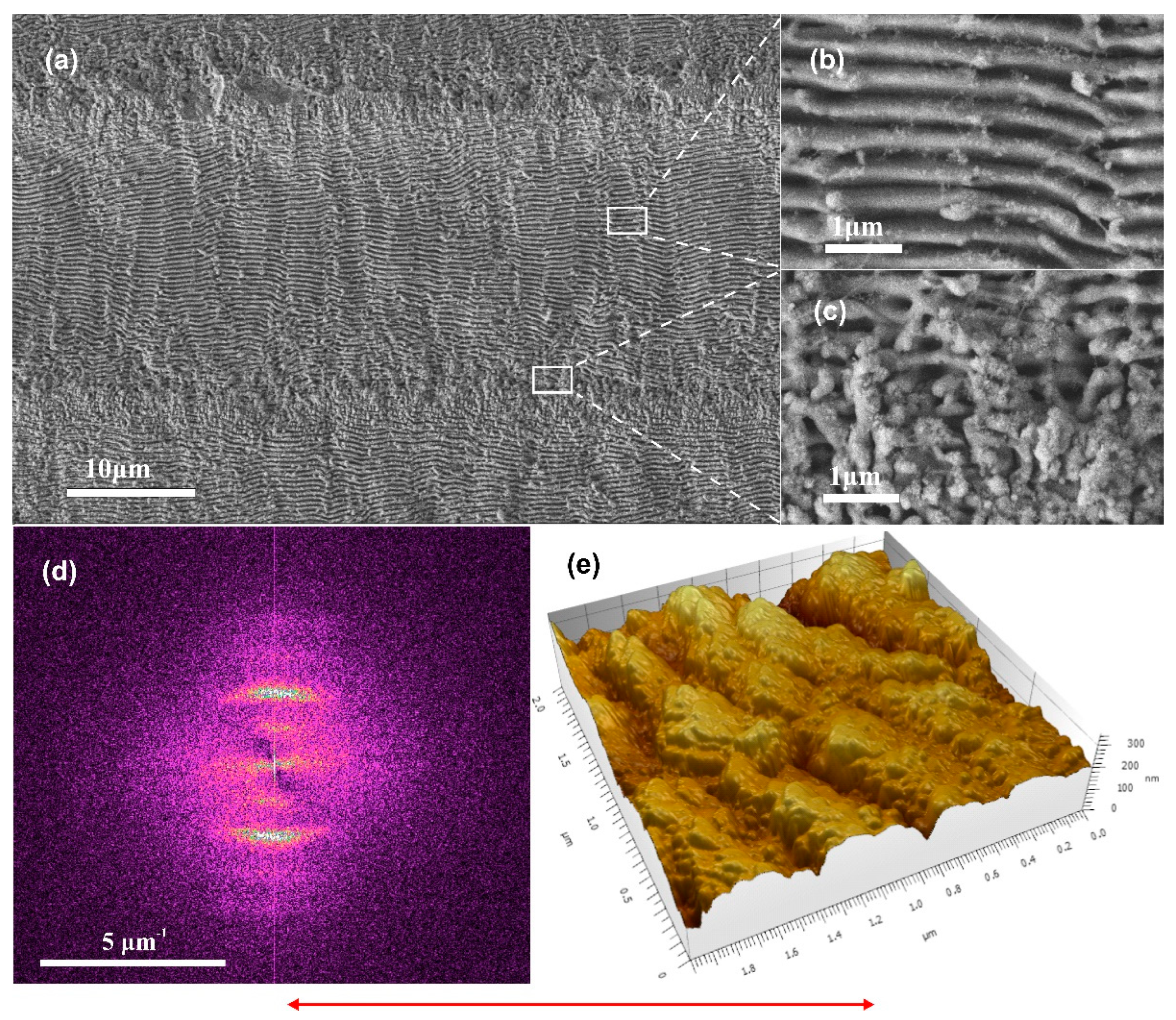
2. Since the single line analysis revealed that the width of the ablated area was found to be ~22 μm the spacing between the lines was fixed to be ∆x = 22 μm. The FESEM image of the HSFL generated on borosilicate glass and the magnified image of the central area of the scan line and the overlapping area of the two-scan line is also shown in
Figure 5a‒c. The interface of the two lines is observed to be losing its periodicity and this is due to the incubation effect. The 2D Fourier transform (FFT) (
Figure 5d) of the large area shows that the periodicity of the HSFL is ~380 nm. Also, the AFM measurements (
Figure 5e) reveals that the depth of the grooves are ~130 nm.
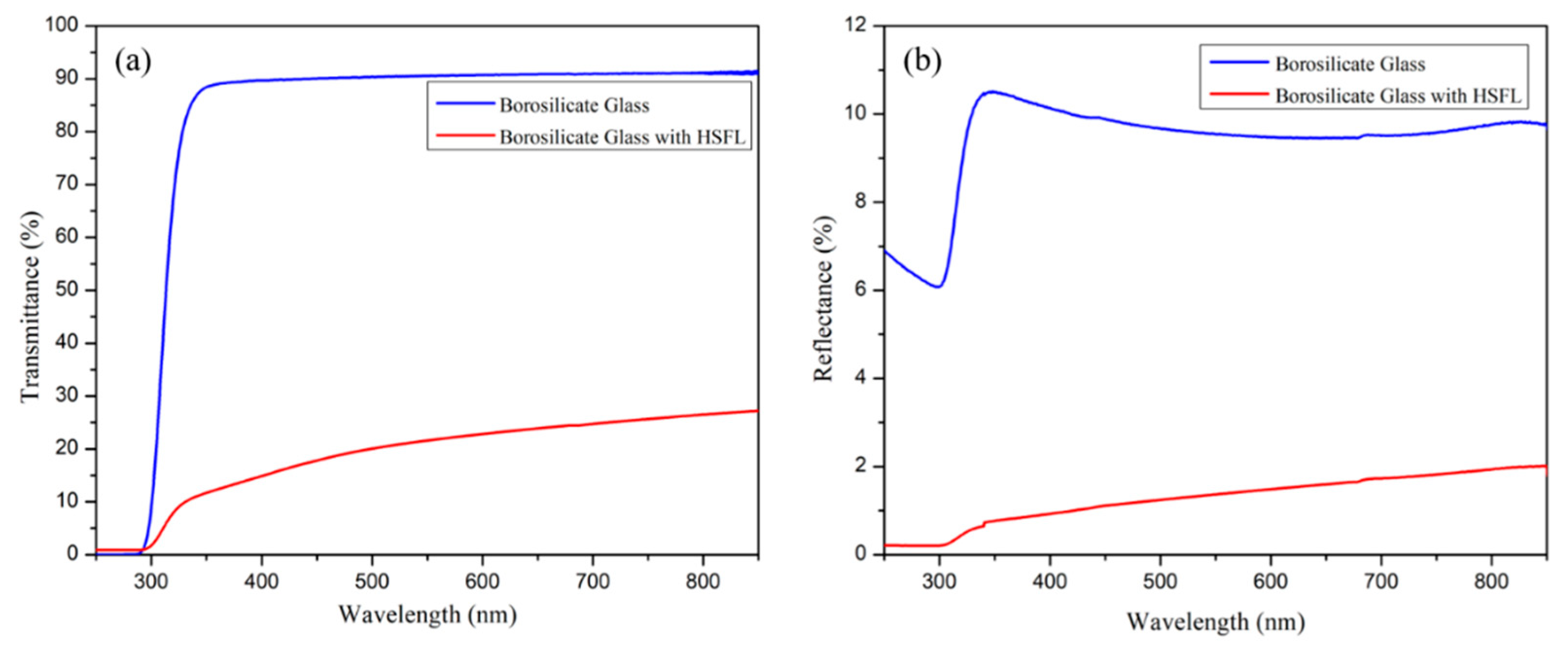
The transmittance and total reflectance of the surface structured borosilicate glass were measured and compared with the unstructured borosilicate glass. As shown in
Figure 7a,b the transmittance and the reflectance of the glass surface were significantly reduced after HSFL formation. This may be due to the scattering or absorption by the micro/nanostructures, and degradation of material property by laser irradiation [
34]. The low reflectivity of the material surface can be attributed to the anti-reflective properties of the periodic structures, which have been discussed in multiple investigations [
49,
50]. The reduction in the transmission can be attributed to be due to the crystal formation at the surface of the glass, which alters the absorption characteristics of the incident radiation [
51].
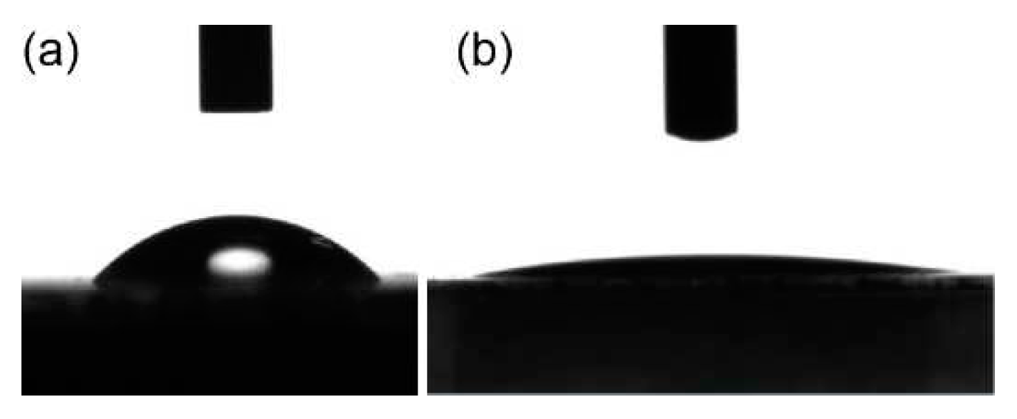
The wettability of the structured borosilicate glass is compared with the unstructured borosilicate glass by taking the contact angle measurement(
Figure 8a,b). The initial, non-irradiated borosilicate glass surface is characterized by a contact angle of
θ ≈ 42
0, which corresponds to the hydrophilic behavior of the glass surface. After the formation of HSFL, the contact angle was decreased to
θ ≈ 8
0, which corresponds to a superhydrophilic behavior of the surface. This super hydrophilic behavior of borosilicate glass with HSFL can be explained using Wenzel’s model, it takes into account how the roughness factor
r affects the contact angle of an initially flat surface according to the equation
cos θw = r cos θ [
52], where the roughness factor
r is the ratio of actual surface area to the geometrical surface area. So according to this relation the theoretical roughness factor can be estimated as
r = 1.33. But from the AFM measurements the roughness factor can be estimated as
r = 1.35. This deviation in the roughness factor is due to the fact that the Wenzel model only considers the topographical aspects whereas Kietzig et al. reported that the surface chemistry also has significant effect on wetting properties [
53].
5. Conclusions
We investigated the generation of high spatial frequency laser-induced periodic surface structures (HSFL) on borosilicate glass using femtosecond laser pulses. The effects of laser fluence (F), number of laser shots (N), and scan direction with respect to laser polarization on large-area surface structuring were thoroughly investigated. We measured the single pulse ablation threshold (Fth=3.87±0.26 J/cm2) and incubation factor (S=0.68±0.03) of Borosilicate glasses for precise control for large area surface structuring. Single-spot experiments show that uniform LIPSS formation is limited by melt and crater formation inside the irradiated area for higher fluence and a larger number of irradiated laser pulses. The optimized conditions were used to create large areas of high-spatial-frequency laser-induced periodic surface structures (HSFLs) with a periodicity of approximately 380 nanometers. The induced structures were oriented parallel to the electric field vector. Scanning in the same direction as the laser polarization results in more uniform surface structuring. The significant change in the reflection and transmittance of processed borosilicate glass, as well as the change in wettability from hydrophilic to superhydrophilic, demonstrates the potential of large area-HSFL structures in optics, microfluidics, photovoltaics, and biomaterials.
Author Contributions
Conceptualization, R.R. and K.K.A; methodology, R.R.; validation, R.R., E.R.K. and K.K.A.; formal analysis, R.R.; investigation, R.R.; resources, R.R. and K.K.A.; data curation, R.R. and E.R.K; writing—original draft preparation, R.R. and E.R.K; writing—review and editing, K.K.A.; supervision, K.K.A.; project administration, K.K.A.; funding acquisition, K.K.A.; All authors have read and agreed to the published version of the manuscript.
Funding
RR acknowledges the University Grand Commission (UGC), Govt. of India, for Junior Research Fellowship for PhD program [NTA Ref. No.: 191620101085]. This research was supported by the Chancellor's Award Grant (267/2021/HEDN, No.CUSAT/PL(B).A3/1793/2021) from the Government of Kerala.
Acknowledgments
The research work presented in this paper was supported by the Chancellor's Award Grant (267/2021/HEDN, No.CUSAT/PL(B).A3/1793/2021) from the Government of Kerala. The authors would also like to extend their appreciation to the Inter-University Centre for Nanomaterials and Devices (IUCND) and the Centre of Excellence in Advanced Materials (CAM) for providing the necessary experimental facilities. R. R. acknowledges the valuable assistance of Mr. Arun G (Technical Assistant, Department of Physics, CUSAT) and Mr. Arun Pappachan (Research Scholar, International School of Photonics, CUSAT) for their contributions in FESEM and UV-VIS-NIR Spectrophotometer measurements, respectively.
Conflicts of Interest
The authors declare no conflict of interest.
References
- Bonse, J.; Kirner, S. V; Höhm, S.; Epperlein, N.; Spaltmann, D.; Rosenfeld, A.; Krüger, J. Applications of Laser-Induced Periodic Surface Structures (LIPSS). In Proceedings of the Laser-based Micro- and Nanoprocessing XI; Klotzbach, U., Washio, K., Kling, R., Eds.; SPIE, 2017; Vol. 10092, p. 100920N.
- Vorobyev, A.Y.; Guo, C. Direct Femtosecond Laser Surface Nano/Microstructuring and Its Applications. Laser Photon Rev 2013, 7, 385–407. [CrossRef]
- Bonse, J.; Koter, R.; Hartelt, M.; Spaltmann, D.; Pentzien, S.; Höhm, S.; Rosenfeld, A.; Krüger, J. Femtosecond Laser-Induced Periodic Surface Structures on Steel and Titanium Alloy for Tribological Applications. Appl Phys A Mater Sci Process 2014, 117, 103–110. [CrossRef]
- Yang, J.; Yang, Y.; Zhao, B.; Wang, Y.; Zhu, X. Femtosecond Laser-Induced Surface Structures to Significantly Improve the Thermal Emission of Light from Metals. Appl Phys B 2012, 106, 349–355. [CrossRef]
- Shukla, P.; Waugh, D.G.; Lawrence, J.; Vilar, R. 10 - Laser Surface Structuring of Ceramics, Metals and Polymers for Biomedical Applications: A Review. In Laser Surface Modification of Biomaterials; Vilar, R., Ed.; Woodhead Publishing, 2016; pp. 281–299 ISBN 978-0-08-100883-6.
- Sipe, J.E.; Young, J.F.; Preston, J.S.; van Driel, H.M. Laser-Induced Periodic Surface Structure. I. Theory. Phys Rev B 1983, 27, 1141–1154. [CrossRef]
- Bonse, J.; Krüger, J.; Höhm, S.; Rosenfeld, A. Femtosecond Laser-Induced Periodic Surface Structures. J Laser Appl 2012, 24, 042006. [CrossRef]
- Ou, Z.; Huang, M.; Zhao, F. The Fluence Threshold of Femtosecond Laser Blackening of Metals: The Effect of Laser-Induced Ripples. Opt Laser Technol 2016, 79, 79–87. [CrossRef]
- Nivas, J.J.J.; Amoruso, S. Generation of Supra-Wavelength Grooves in Femtosecond Laser Surface Structuring of Silicon. Nanomaterials 2021, 11. [CrossRef]
- Höhm, S.; Rosenfeld, A.; Krüger, J.; Bonse, J. Femtosecond Laser-Induced Periodic Surface Structures on Silica. J Appl Phys 2012, 112. [CrossRef]
- Bonse, J.; Hohm, S.; Kirner, S. V.; Rosenfeld, A.; Kruger, J. Laser-Induced Periodic Surface Structures-A Scientific Evergreen. IEEE Journal of Selected Topics in Quantum Electronics 2017, 23, 109–123. [CrossRef]
- Reif, J.; Costache, F.; Henyk, M.; Pandelov, S. V Ripples Revisited: Non-Classical Morphology at the Bottom of Femtosecond Laser Ablation Craters in Transparent Dielectrics. Appl Surf Sci 2002, 197–198, 891–895. [CrossRef]
- Bonse, J.; Krüger, J. Pulse Number Dependence of Laser-Induced Periodic Surface Structures for Femtosecond Laser Irradiation of Silicon. J Appl Phys 2010, 108. [CrossRef]
- Bonse, J.; Rosenfeld, A.; Krüger, J. On the Role of Surface Plasmon Polaritons in the Formation of Laser-Induced Periodic Surface Structures upon Irradiation of Silicon by Femtosecond-Laser Pulses. J Appl Phys 2009, 106. [CrossRef]
- Liang, F.; Vallée, R.; Chin, S.L. Mechanism of Nanograting Formation on the Surface of Fused Silica. Opt Express 2012, 20, 4389. [CrossRef]
- Liao, Y.; Ni, J.; Qiao, L.; Huang, M.; Bellouard, Y.; Sugioka, K.; Cheng, Y. High-Fidelity Visualization of Formation of Volume Nanogratings in Porous Glass by Femtosecond Laser Irradiation. Optica 2015, 2, 329–334. [CrossRef]
- Le Harzic, R.; Dörr, D.; Sauer, D.; Neumeier, M.; Epple, M.; Zimmermann, H.; Stracke, F. Large-Area, Uniform, High-Spatial-Frequency Ripples Generated on Silicon Using a Nanojoule-Femtosecond Laser at High Repetition Rate; 2011;
- Dufft, D.; Rosenfeld, A.; Das, S.K.; Grunwald, R.; Bonse, J. Femtosecond Laser-Induced Periodic Surface Structures Revisited: A Comparative Study on ZnO. J Appl Phys 2009, 105. [CrossRef]
- Jia, T.Q.; Chen, H.X.; Huang, M.; Zhao, F.L.; Qiu, J.R.; Li, R.X.; Xu, Z.Z.; He, X.K.; Zhang, J.; Kuroda, H. Formation of Nanogratings on the Surface of a ZnSe Crystal Irradiated by Femtosecond Laser Pulses. Phys Rev B Condens Matter Mater Phys 2005, 72. [CrossRef]
- Hnatovsky, C.; Taylor, R.S.; Simova, E.; Rajeev, P.P.; Rayner, D.M.; Bhardwaj, V.R.; Corkum, P.B. Fabrication of Microchannels in Glass Using Focused Femtosecond Laser Radiation and Selective Chemical Etching. Appl Phys A Mater Sci Process 2006, 84, 47–61. [CrossRef]
- Huang, M.; Zhao, F.; Cheng, Y.; Xu, N.; Xu, Z. Mechanisms of Ultrafast Laser-Induced Deep-Subwavelength Gratings on Graphite and Diamond. Phys Rev B Condens Matter Mater Phys 2009, 79. [CrossRef]
- Das, S.K.; Messaoudi, H.; Debroy, A.; McGlynn, E.; Grunwald, R. Multiphoton Excitation of Surface Plasmon-Polaritons and Scaling of Nanoripple Formation in Large Bandgap Materials. Opt Mater Express 2013, 3, 1705. [CrossRef]
- Huang, M.; Zhao, F.; Cheng, Y.; Xu, N.; Xu, Z. Origin of Laser-Induced near-Subwavelength Ripples: Interference between Surface Plasmons and Incident Laser. ACS Nano 2009, 3, 4062–4070. [CrossRef]
- Borowiec, A.; Haugen, H.K. Subwavelength Ripple Formation on the Surfaces of Compound Semiconductors Irradiated with Femtosecond Laser Pulses. Appl Phys Lett 2003, 82, 4462–4464. [CrossRef]
- Taher, M.A.; Chaudhary, N.; Thirunaukkarasu, K.; Rajput, V.K.; Naraharisetty, S.R.G. Controlled Periodicities of Ladder-like Structures via Femtosecond Laser of Wavelength from 400 Nm to 2200 Nm. Surfaces and Interfaces 2022, 28. [CrossRef]
- Maragkaki, S.; Derrien, T.J.Y.; Levy, Y.; Bulgakova, N.M.; Ostendorf, A.; Gurevich, E.L. Wavelength Dependence of Picosecond Laser-Induced Periodic Surface Structures on Copper. Appl Surf Sci 2017, 417, 88–92. [CrossRef]
- Shi, X.; Xu, X. Laser Fluence Dependence of Ripple Formation on Fused Silica by Femtosecond Laser Irradiation. Appl Phys A Mater Sci Process 2019, 125. [CrossRef]
- Gregorčič, P.; Sedlaček, M.; Podgornik, B.; Reif, J. Formation of Laser-Induced Periodic Surface Structures (LIPSS) on Tool Steel by Multiple Picosecond Laser Pulses of Different Polarizations. Appl Surf Sci 2016, 387, 698–706. [CrossRef]
- Gräf, S.; Kunz, C.; Engel, S.; Derrien, T.J.Y.; Müller, F.A. Femtosecond Laser-Induced Periodic Surface Structures on Fused Silica: The Impact of the Initial Substrate Temperature. Materials 2018, 11. [CrossRef]
- Albu, C.; Dinescu, A.; Filipescu, M.; Ulmeanu, M.; Zamfirescu, M. Periodical Structures Induced by Femtosecond Laser on Metals in Air and Liquid Environments. Appl Surf Sci 2013, 278, 347–351. [CrossRef]
- Nürnberger, P.; Reinhardt, H.; Kim, H.C.; Yang, F.; Peppler, K.; Janek, J.; Hampp, N. Influence of Substrate Microcrystallinity on the Orientation of Laser-Induced Periodic Surface Structures. J Appl Phys 2015, 118. [CrossRef]
- Kunz, C.; Engel, S.; Müller, F.A.; Gräf, S. Large-Area Fabrication of Laser-Induced Periodic Surface Structures on Fused Silica Using Thin Gold Layers. Nanomaterials 2020, 10, 1–14. [CrossRef]
- Choi, J.; Schwarz, C. Advances in Femtosecond Laser Processing of Optical Material for Device Applications. Int J Appl Glass Sci 2020, 11, 480–490. [CrossRef]
- Xu, S. zhen; Dou, H. qiang; Sun, K.; Ye, Y. yun; Li, Z.; Wang, H. jun; Liao, W.; Liu, H.; Miao, X. xiang; Yuan, X. dong; et al. Scan Speed and Fluence Effects in Femtosecond Laser Induced Micro/Nano-Structures on the Surface of Fused Silica. J Non Cryst Solids 2018, 492, 56–62. [CrossRef]
- Schwarz, S.; Rung, S.; Esen, C.; Hellmann, R. Surface Plasmon Polariton Triggered Generation of 1D-Low Spatial Frequency LIPSS on Fused Silica. Applied Sciences (Switzerland) 2018, 8. [CrossRef]
- Gräf, S.; Kunz, C.; Müller, F.A. Formation and Properties of Laser-Induced Periodic Surface Structures on Different Glasses. Materials 2017, 10. [CrossRef]
- Richter, S.; Miese, C.; Döring, S.; Zimmermann, F.; Withford, M.J.; Tünnermann, A.; Nolte, S. Laser Induced Nanogratings beyond Fused Silica - Periodic Nanostructures in Borosilicate Glasses and ULETM. Opt Mater Express 2013, 3, 1161. [CrossRef]
- Liu, J.M. Simple Technique for Measurements of Pulsed Gaussian-Beam Spot Sizes. Opt. Lett. 1982, 7, 196–198. [CrossRef]
- Jee, Y.; Becker, M.F.; Walser, R.M. Laser-Induced Damage on Single-Crystal Metal Surfaces. J. Opt. Soc. Am. B 1988, 5, 648–659. [CrossRef]
- Raciukaitis, G.; Brikas, M.; Gecys, P.; Gedvilas, M. Accumulation Effects in Laser Ablation of Metals with High-Repetition-Rate Lasers. In Proceedings of the High-Power Laser Ablation VII; SPIE, May 8 2008; Vol. 7005, p. 70052L.
- Bonse, J.; Sturm, H.; Schmidt, D.; Kautek, W. Chemical, Morphological and Accumulation Phenomena in Ultrashort-Pulse Laser Ablation of TiN in Air. Appl Phys A Mater Sci Process 2000, 71, 657–665. [CrossRef]
- Di Niso, F.; Gaudiuso, C.; Sibillano, T.; Mezzapesa, F.P.; Ancona, A.; Lugarà, P.M. Role of Heat Accumulation on the Incubation Effect in Multi-Shot Laser Ablation of Stainless Steel at High Repetition Rates. Opt Express 2014, 22, 12200. [CrossRef]
- Ben-Yakar, A.; Byer, R.L. Femtosecond Laser Ablation Properties of Borosilicate Glass. J Appl Phys 2004, 96, 5316–5323. [CrossRef]
- Mannion, P.T.; Magee, J.; Coyne, E.; O’Connor, G.M.; Glynn, T.J. The Effect of Damage Accumulation Behaviour on Ablation Thresholds and Damage Morphology in Ultrafast Laser Micro-Machining of Common Metals in Air. Appl Surf Sci 2004, 233, 275–287. [CrossRef]
- Neuenschwander, B.; Jaeggi, B.; Schmid, M.; Dommann, A.; Neels, A.; Bandi, T.; Hennig, G. Factors Controlling the Incubation in the Application of Ps Laser Pulses on Copper and Iron Surfaces. In Proceedings of the Laser Applications in Microelectronic and Optoelectronic Manufacturing (LAMOM) XVIII; Xu, X., Hennig, G., Nakata, Y., Roth, S.W., Eds.; SPIE, 2013; Vol. 8607, p. 86070D.
- Ben-Yakar, A.; Harkin, A.; Ashmore, J.; Byer, R.L.; Stone, H.A. Thermal and Fluid Processes of a Thin Melt Zone during Femtosecond Laser Ablation of Glass: The Formation of Rims by Single Laser Pulses. J Phys D Appl Phys 2007, 40, 1447–1459. [CrossRef]
- Laville, S.; Vidal, F.; Johnston, T.W.; Chaker, M.; Le Drogoff, B.; Barthélemy, O.; Margot, J.; Sabsabi, M. Modeling the Time Evolution of Laser-Induced Plasmas for Various Pulse Durations and Fluences. Phys Plasmas 2004, 11, 2182–2190. [CrossRef]
- Ben-Yakar, A.; Byer, R.L.; Harkin, A.; Ashmore, J.; Stone, H.A.; Shen, M.; Mazur, E. Morphology of Femtosecond-Laser-Ablated Borosilicate Glass Surfaces. Appl Phys Lett 2003, 83, 3030–3032. [CrossRef]
- Raguin, D.H.; Morris, G.M. Antireflection Structured Surfaces for the Infrared Spectral Region. Appl. Opt. 1993, 32, 1154–1167. [CrossRef]
- Grann, E.B.; Moharam, M.G.; Pommet, D.A. Optimal Design for Antireflective Tapered Two-Dimensional Subwavelength Grating Structures. J. Opt. Soc. Am. A 1995, 12, 333–339. [CrossRef]
- Yilbas, B.S.; Khaled, M.; Abu-Dheir, N.; Al-Aqeeli, N.; Said, S.A.M.; Ahmed, A.O.M.; Varanasi, K.K.; Toumi, Y.K. Wetting and Other Physical Characteristics of Polycarbonate Surface Textured Using Laser Ablation. Appl Surf Sci 2014, 320, 21–29. [CrossRef]
- Wenzel, R.N. RESISTANCE OF SOLID SURFACES TO WETTING BY WATER. Ind Eng Chem 1936, 28, 988–994. [CrossRef]
- Kietzig, A.M.; Hatzikiriakos, S.G.; Englezos, P. Patterned Superhydrophobic Metallic Surfaces. Langmuir 2009, 25, 4821–4827. [CrossRef]
|
Disclaimer/Publisher’s Note: The statements, opinions and data contained in all publications are solely those of the individual author(s) and contributor(s) and not of MDPI and/or the editor(s). MDPI and/or the editor(s) disclaim responsibility for any injury to people or property resulting from any ideas, methods, instructions or products referred to in the content. |
© 2023 by the authors. Licensee MDPI, Basel, Switzerland. This article is an open access article distributed under the terms and conditions of the Creative Commons Attribution (CC BY) license (http://creativecommons.org/licenses/by/4.0/).
