1. Introduction
Carbon materials such as graphene, MWCNTs, and AC have significant advantages for energy storage [
12,
13]. AC with a large surface area, has been widely used as the main electrode in many past studies in powders, aerogels, and fibres [
14]. However, it has several disadvantages when used at temperatures that are too low or too high, exhibiting a significant decrease in energy density. As a result AC needs to be combined with other materials with good conductivity, large specific surface area, and stability at extreme temperatures [
15].
MWCNTs have many advantages, such as unique cavity structure, good electrical conductivity, high specific surface area, good chemical stability, and porosity suitable for electrolyte ion transfer [
16,
17]. They are commonly used to increase the electrical conductivity in supercapacitors and batteries. Their structure has a nanometer scale size in the form of coils of carbon that bind to each other, significantly increasing power density of the supercapacitor as an electrode material. Moreover, recent studies have shown that MWCNTs synthesis can improve cycle life and specific capacitance because ions are entangled in the mesoporous of nanotube chains [
18,
19].
In the development of supercapacitors, electrolytes play an essential role in electron transfer and balance between two electrodes [
20]. They are classified into several categories: aqueous, organic, liquid-ions, solid-state, and quasi-solid-state with controlled redox reactions. Moreover, the electrolyte concentration will significantly affect the performance of the electrolyte.
An activated carbon-carbon nanotube (AC-CNT) composite was synthesized using a simple chemical process, and its electrochemical performance in different aqueous electrolytes, such as H
2SO
4, Na
2SO
4, and KOH, was investigated. The composite exhibited different capacitive behaviours in various aqueous electrolytes, demonstrating the highest specific capacitance in the H
2SO
4 electrolyte because of its high molar ionic conductivity compared to the other two. Nyquist and Bode plots indicated that the composite in the H
2SO
4 electrolyte had the lowest electrochemical impedance and highest capacitive behaviours compared to the others. The composite in the Na
2SO
4 electrolyte has the lowest capacitance, owing to the low molar ionic conductivity of the electrolyte, although it displayeds the best capacitance retention after 200 cycles. The selection of electrolytes, therefore, is a vital factor for supercapacitor applications [
20].
Double-layer formation involves the migration of electrolyte ions into the pores of the electrode. This mobility decreases when using very high electrolyte concentrations. However, if the electrolyte concentration is too low, the amount of ionic charge will not be sufficient for the double layer. Therefore, several studies have been performed to optimise the electrolyte concentration to increase the ion transport into the electrode based on MWCNTs material [
21]. Double-layer capacitors fabricated with activated carbon electrodes and filled with non-aqueous electrolytes with different salt concentrations were studied. It was known that the performance of capacitors is highly dependent on the salt concentration in the electrolyte. For electrolytes with high salt concentration, the maximum energy stored in a capacitor is limited by the capacitance of the electrode materials. For low-salt electrolytes, the maximum operating voltage and maximum energy decrease with decreasing salt concentration. AC impedance measurements demonstrate that the drop in maximum energy was due to depletion of free ions in the electrolyte. Based on analysis of DC charge and discharge cycles at various constant current rates, the power performance of capacitors was also highly dependent on the salt concentration of the electrolyte [
22].
For instance, Jeong et al. [
23] studied the correlation between the electrolyte concentration of electrolyte LiPF
6/PC and supercapacitor performance and showed that redox reaction was strongly dependent on increasing electrolyte concentration. In addition, Krishnan and Biju studied the effect of electrolyte concentration electrochemical performance of RGO-Na
2SO
4 in an aqueous solution and achieved the best energy and power density at 1 M concentration [
24]. Furthermore, a study was carried out to find out the effect of electrolyte concentration on the electrochemical performance of reduced graphite oxide–potassium hydroxide supercapacitor. The supercapacitor achieveds a maximum specific capacitance with electrolyte 6 M KOH. The kinetics of charge storage revealeds that the combination of the surface phenomenon and intercalation process leads to maximum specific capacitance [
25].
The effects of several experimental conditions, such as electrode layer binder content, conducting carbon content, electrode layer thickness, as well as electrolyte concentration, on both the specific capacitance and energy density of a BP2000 carbon-based supercapacitor are investigated using both cyclic voltammetry and a galvanic charging–discharging curve. The electrode layer studied contains Super C45 carbon as the conducting additive, PTFE as the binder, and Na
2SO
4 as the aqueous electrolyte, respectively. Regarding the effect of electrolyte concentration in the range of 0.1–1.0 M, 0.5 M of Na
2SO
4 gives the best performance [
26].
In this study, Na
2SO
4 was also chosen as an electrolyte because it is a less corrosive material with a large potential window (1.8 V). Na
2SO
4 is an aqueous solution electrolyte that exhibits good conductivity and safety as a coating that does not allow the peeling of the composite material from the surface of deposited material [
5]. Composite synthesis was carried out by combining MWCNTs and AC with a simple method of physical chemistry and adding poly(vinylidene fluoride) (PVDF) as a binder. Furthermore, the synthesized composite was deposited on top of the Cu substrate using the doctor blade method. In addition, analysis was conducted of morphological and electrochemical properties, such as cyclic voltametry (CV) and electrochemical impedance spectroscopy (EIS) in various Na
2SO
4 electrolyte concentrations.
2. Materials and Methods
We purchased MWCNTs from the nanotechnology laboratory at Universitas Diponegoro. According to the product specification, these MWCNTs have a multi-walled shape without functionalised with a diameter of less than 10 nm. AC purchased from Sigma-Aldrich had a specification surface area of 1000 m2/g and particle size distribution of around 74 μm for 15% and 10 μm for 75%. The solvent that disperseds MWCNTs and AC was n-methyl-2-pyrrolidinone from Sigma-Aldric with PVDF as a binder.
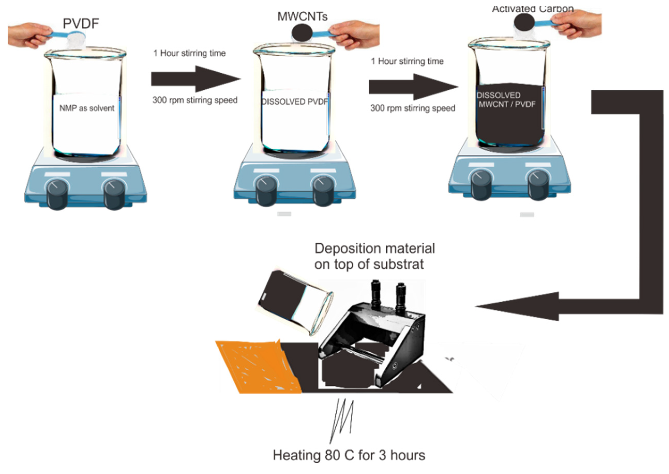
For the sample, we first prepared all the ingredients and weighed them according to the ratio between MWCNTs, AC, and PVDF of 67.5:22.5:10 with a total amount of 1 g for a single synthesis. Next, electrode manufacturing was accomplished by mixing PVDF binders with
N-Methyl-2-pyrrolidone (NMP) solvent stirred for 1 h at 300 rpm at 25°C. Then, we added AC to the solution and stirred for 1 h at 300 rpm at 25°C. After the AC solution was completely dissolved, MWCNTs were added to the solution and stirred for 24 h at 300 rpm at 25°C. After the solution became a homogeneous slurry, the slurry was deposited on the top of copper foil using the doctor blade method with a micrometre adjustable film application. Finally, the deposition material was calcinated at 80°C for 3 h.
Figure 1 illustrates the synthesis of MWCNTs/AC and deposition on the copper foil as substrate.
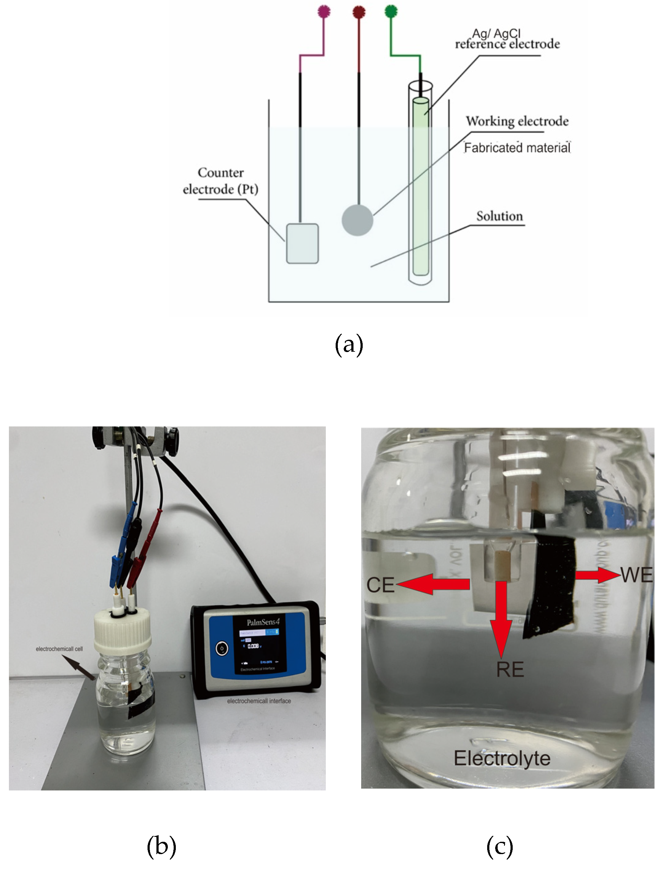
Electrochemical analysis, such as CV and EIS of MWCNTs/AC electrodes, was performed using a potentiostat (Palmsense 4, USA). All measurements were carried out in a three-electrode electrochemical cell configuration, which included a platinum plate (15 x 15 x 1.5 mm) as a counter electrode, Ag/AgCl as a reference electrode, and the synthesized material (17 x 17 x 0.025 mm) as the working electrode. The CV was performed in an applied voltage window of –1.0 to 0.1 V at a scan rate of 50 mV/s. For the EIS analysis, we took measurements at frequencies of 1 to 100,000 Hz. All the measurements were performed with various electrolytes of Na2SO4 of 1 to 6 M. This technique allowed a better understanding by transposing the system into an equivalent electrical circuit.
3. Results and Discussions
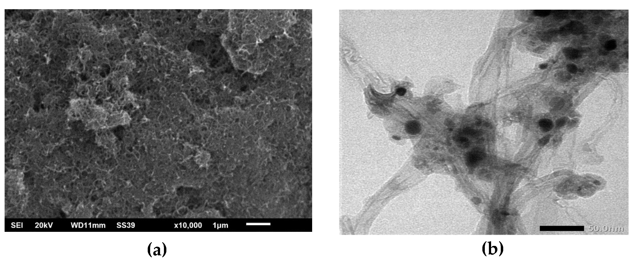
Electrode surface morphology was obtained by SEM analysis. The results of surface morphological images can show a correlation between the structures formed and the results of electrode electrochemical analysis. The SEM results in
Figure 2a show the distribution of MWCNTs with tube structures in the AC materials. MWCNTs with a diameter of 1-10 nm could easily infiltrate pores from AC on the micrometre scale. This infiltration causeds electrons that were previously difficult to pass through the pore of AC to be easily passed. The result also showed no uniform morphology, and the orientation was random. This causeds roughness of the surface electrode, affecting the electrochemical performance.
Furthermore, to analyse the shape and size of the MWCNTs, TEM analysis can determine if the size was formed on the nanometer scale. The result from the TEM analysis in
Figure 2b shows MWCNTs diameters less than 20 nm. The result also showed AC sticking to the body of MWCNTs.
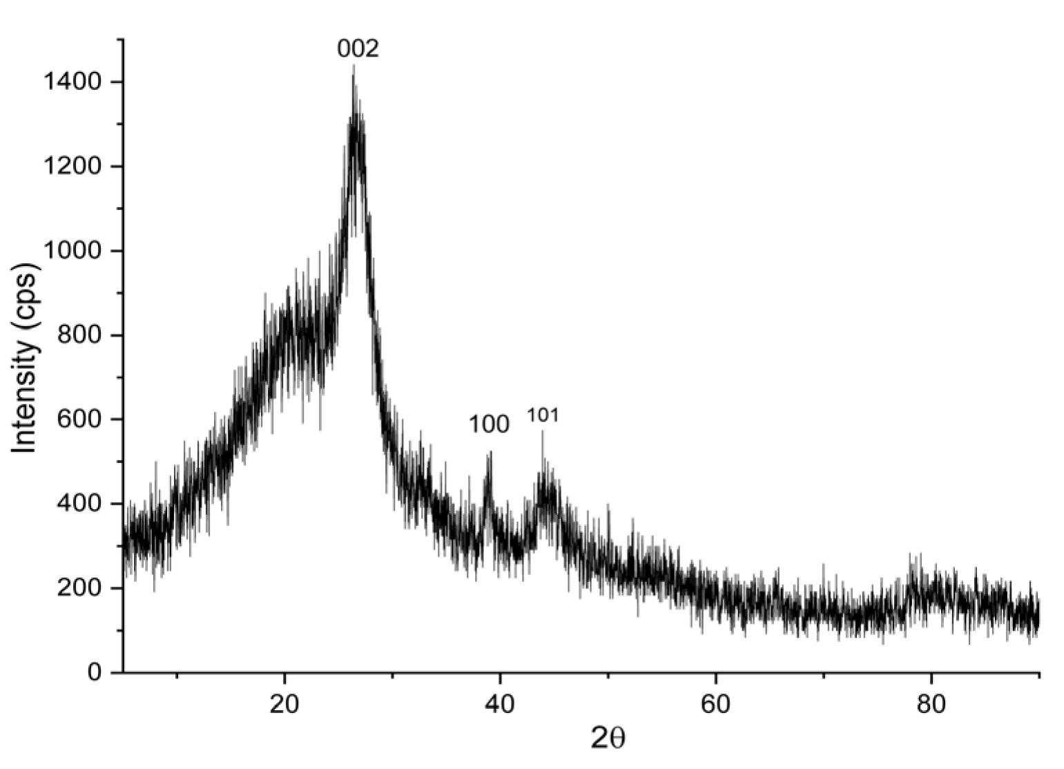
The crystalline structure of the composite was analysed by X-ray diffraction (XRD) at 40 kV with Cu K radiation (λ = 1.54 Å) using an automated X-ray diffractometer (D/MAX-2500/PC, Rigaku, Japan).
Figure 3 shows the results of the XRD testing of MWCNTs/AC. The XRD pattern shows intense peaks at 2θ = 25.5° which corresponds to the
hkl index of (002), 43.2° (100), and 56.9° (101).
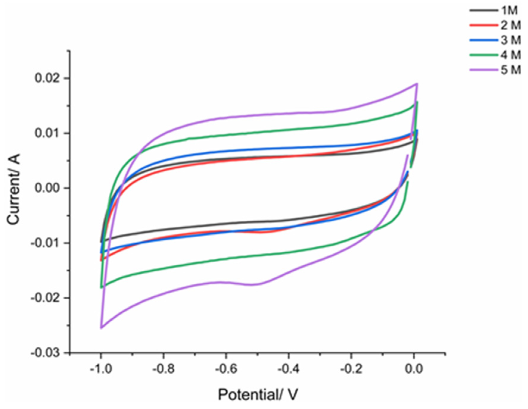
An analysis of cyclic voltammetry was used to obtain the specific capacitance of the electrode. The measurement was carried out at a scan rate of 50 mV/s with a potential range of -1.0 to 0.1 V in various concentrations of the electrolyte Na
2SO
4 solution (1 to 6 M). A three-electrode system was used in this research. We applied a reference electrode type of Ag/AgCl within KCL 1 M as the solution inside the electrode. For the counter electrode, we chose platinum cause of its good electrochemical inertness, conductivity, and stability.
Figure 4 shows the measurement scheme for electrochemical performance.
To measure the specific capacitance after obtaining the CV plot, we can use the following equation:
where
Cs is specific capacitance (F/g),
m is the mass of electrode (g),
k is scan rate of measurement (V/s),
V1 is the first potential where the scan is forwarded, and
V2 is the second potential where the scan is reversed [
27].
This research used a cyclic voltammogram to determine and shows where the increase in electrolyte concentration increases the diagram area. Tests are performed on a range of electrolyte concentration form 1-5M. However, there has been damage to the surface of the electrode using an electrolyte concentration of 6 M so that no curve was obtained. The CV curves are rectangular shaped as concentration of electrolyte increases. For all concentration of Na2SO4, the CV is quasi-rectangular, and 5M concentration given largest area of CV diagram.
The EIS measurements were carried out over a frequency range of 10,000 to 1 Hz.
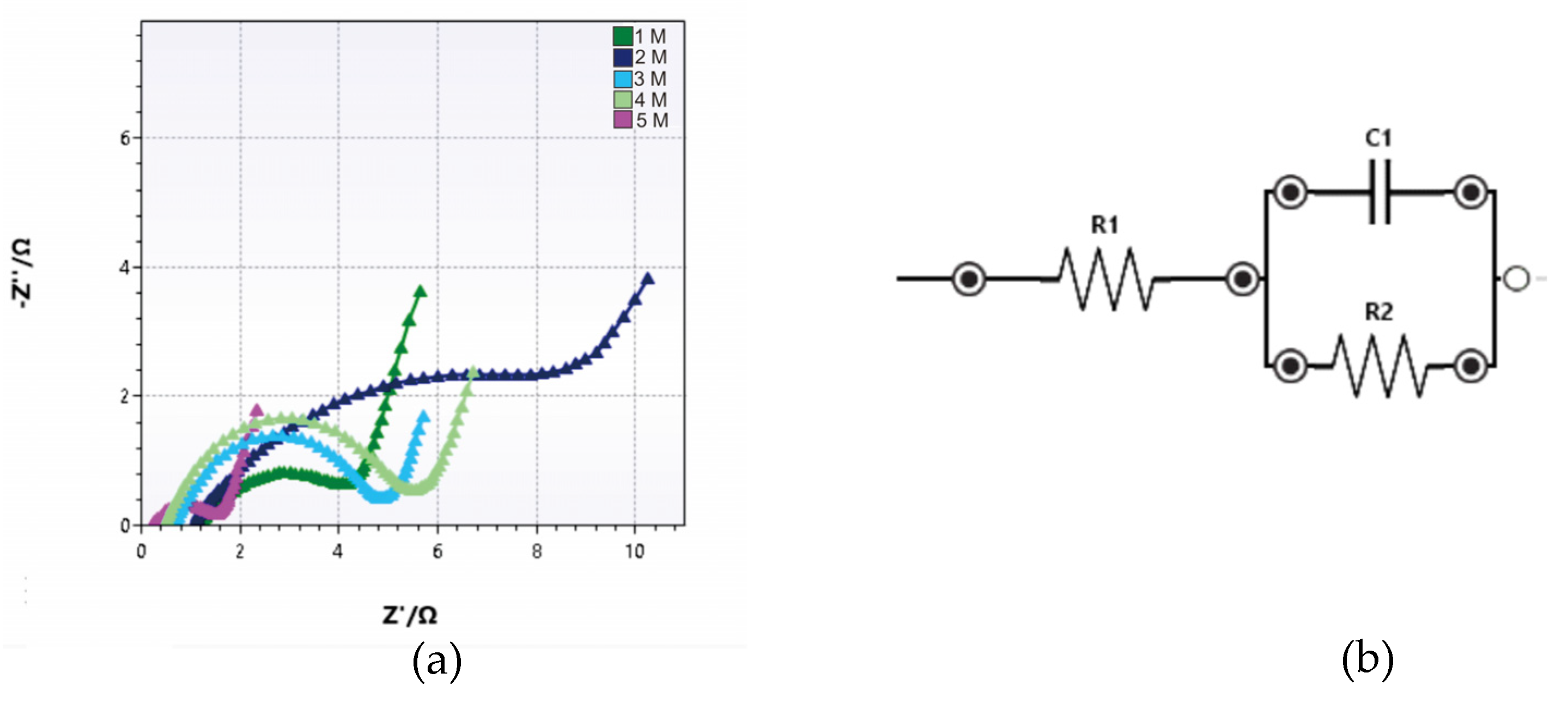
Figure 6 shows the corresponding Nyquist plot of the electrode measurement. From the Nyquist plot, we can analyse the result using an EIS analyser where the cole-cole is fitted with the equivalent circuit model.
Figure 6 also shows the trend of the intercept value on the Nyquist plot which is in contrast to the increase in the electrolyte concentration of the solution. The intercept gives the values of 0.230, 0.690, 0.725, 1.080 and 1.225 Ω for the concentrations of 5, 4, 3, 2, and 1 M, respectively. The value at intercept (Rs) is defined as the sum of the contact resistances (between the electrode and the current collector) and electrolyte resistance. It was observed that the value of Z’ (real impedance) at the intercept on the real axis decreased as the concentration increased [
21].
From data fitting, we can obtain a value of R1 (Rel - electrolyte resistance) and R2 (Rct - charge transfer resistance).. The fitting data of EIS are presented in table 2.
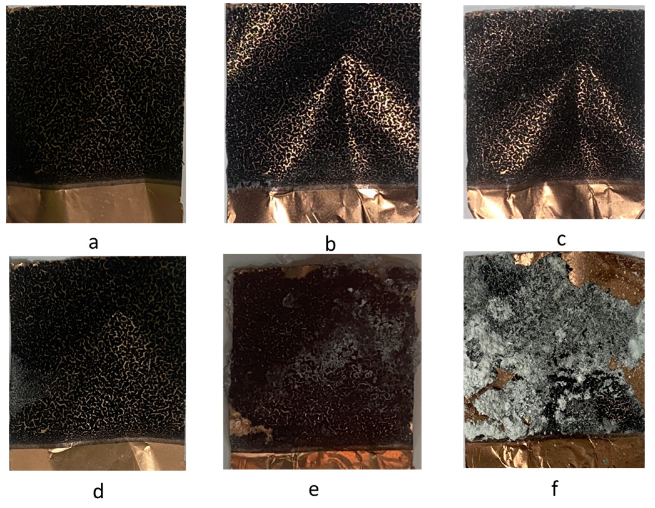
Furthermore, physical observations of the surface of the supercapacitor electrodes were carried out after electrochemical measurements to observe peeling and corrosion that might appear. In
Figure 7 it can be seen that an increase in electrolyte concentration causes the appearance of peeling of the coating from the substrate in samples using an electrolyte concentration of 6 M (
Figure 7f). However, an increase in concentration up to 5 M produces an increased specific capacitance value. The increase in concentration also results in the appearance of deposition on the surface layer of the electrode after measurements are made at certain time intervals. The deposition that appears comes from the Na
2SO
4 salt which does not completely dissolve during the preparation of the electrolyte so that it is easier for the change to become a solid phase. Na
2SO
4 has a unique solubility characteristic where its solubility in water is unusual. Its solubility in water increases more than tenfold at a solubility of 4.97 g/100 mL between 0 and 32.4 °C, and reaches a maximum solubility at 49.7 g/100 mL at 100 °C. So that the optimum concentration that can be made is 3.5 M at 100 °C [
28].
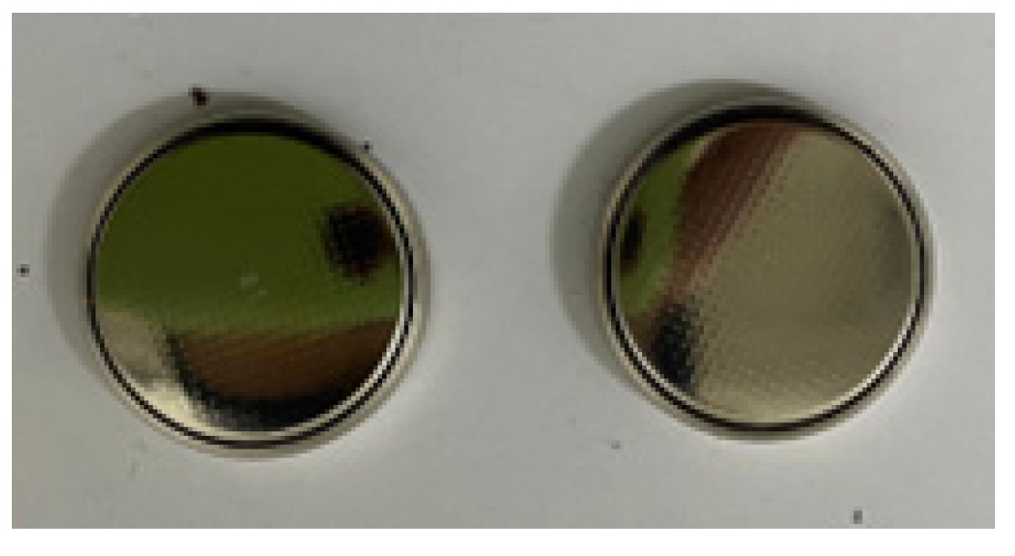
Figure 8 shows supercapacitor coin cell device. For the coin cell device fabrication two electrode configurations were utilized. Both the electrodes were prepared as described in three electrode configurations. The electrodes were separated by a commercially available filter paper soaked in 5 M Na
2SO
4 solution.
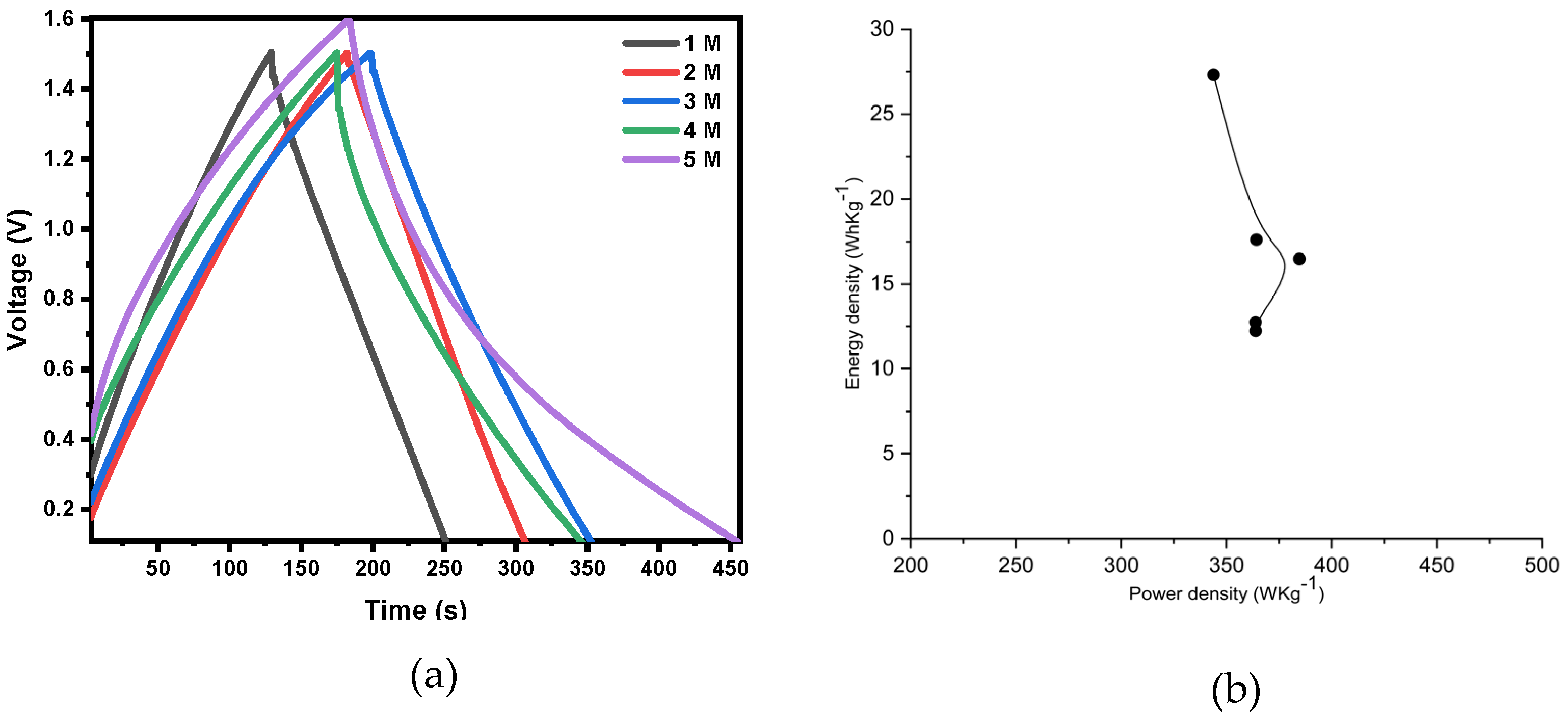
Figure 9a shows the GCD (galvanostatic charge discharge) curve using a current density of 0.1 A/g and a voltage range of 0 to 1.6 V at various electrolyte concentrations. All curves tend to be linear and symmetric, indicating that the electrodes have excellent electrochemical reversibility and charge-discharge properties. The Ragone plot of MWCNTs/activated carbon-based supercapacitor at various electrolyte concentrations is shown in
Figure 9b.
Table 2 shows result of electrochemical properties of cell with various electrolyte concentrations. It has an energy density of 27.312 Wh/kg and a power density of 343.786 W/kg at a current density of 0.1 A/g and the concentration of 5 M Na
2SO
4. The larger energy density in Na
2SO
4 aqueous electrolyte is due to the larger voltage window from 0 to 1.6 V.
5. Conclusions
The electrode was successfully developed by combining the majority MWCNTs within AC using a PVDF binder with a simple method. The material was also deposited on copper foil as substrate. From the morphological analysis, the AC successfully adhered to the MWCNTs. The electrochemical performance obtained using cyclic voltammetry yielded specific capacitances of 34.395, 35.808, 46.284, 49.502, and 76.815 F/g for electrolyte concentration of 1, 2, 3, 4, and 5 M, respectively. At an electrolyte concentration of 5 M Na2SO4, an energy density of 27.312 Wh/Kg and a power density of 343.786 W/Kg were produced. The EIS analysis revealed value for electrolyte resistance and charger transfer resistance that were low, indicating that the material had good conductivity and low resistivity. The increase in electrolyte concentration is limited due to damage to the electrode surface at concentration of 6 M.
Author Contributions
The authors’ contributions are as follows: AS and MD conceptualised, planned, carried out the experiments, and prepared the original draft. HRT contributed to the analysis and interpretation of the article. AP validated and edited the original draft. IL supervised and critically reviewed the research and manuscript. WM contributed to the review and design of experiments. HS provided technical support and guidance. All authors have read and agreed to the published version of the manuscript.
Funding
Institute for Research and Community Services, Universitas Diponegoro, provided funding through the project of RKI 2022 # 434-14/UN7.D2/PP/VI/2022.
Institutional Review Board Statement
All authors confirm that they followed all ethical guidelines. All authors certify that they have no affiliations with or involvement in any organisation or entity with any financial interest or non-financial interest in the subject matter or materials discussed in this manuscript.
Informed Consent Statement
Not applicable.
Data Availability Statement
Data is contained within the article.
Acknowledgements
We are grateful for the support of this work from the Institute for Research and Community Services, Diponegoro University under the project of RKI 2022 with contract number 434-14/UN7.D2/PP/VI/2022.
Conflicts of Interest
The authors declare that they have no conflict of interest.
References
- Lei, C.; Lekakou, C. Activated carbon-carbon nanotube nanocomposite coatings for supercapacitor applications. Surface and Coatings Technology 2013, 232, 326–330. [Google Scholar] [CrossRef]
- Dhas, D.S.; Maldar, P.S.; Patil, M.D.; Nagare, A.B.; Waikar, M.R.; Sonkawade, R.G.; Moholkar, A.V. Synthesis of NiO nanoparticles for supercapacitor application as an efficient electrode material. Vacuum 2020, 181, 109646. [Google Scholar] [CrossRef]
- Madhuri, S.; Chakra, C.S.; Sadhana, K.; Divya, V. Sketchy synthesis of Mn3O4, Mn3O4/AC and Mn3O4/MWCNTS composites for application of/in energy cache. Materials Today: Proceedings 2022, 65, 2812–2818. [Google Scholar]
- Ochai-Ejeh, F.; Madito, M.J.; Makgopa, K.; Rantho, M.N.; Olaniyan, O.; Manyala, N. Electrochemical performance of hybrid supercapacitor device based on birnessite-type manganese oxide decorated on uncapped carbon nanotubes and porous activated carbon nanostructures. Electrochimica Acta 2018, 289, 363–375. [Google Scholar] [CrossRef]
- Lota, K.; Siercynska, A.; Acnik, I. Effect of aqueous electrolytes on electrochemical capacitor capacitance. CHEMIK. 2013, 67, 1138–1145. [Google Scholar]
- Mandal, M.; Subudhi, S.; Alam, I.; Subramanyam, B.V.R.S.; Patra, S.; Raiguru, J.; Das, S.; Mahanandia, P. Facile synthesis of new hybrid electrode material based on activated carbon/multi-walled carbon nanotubes@ZnFe2O4 for supercapacitor applications. Inorganic Chemistry Communications 2021, 123, 108332. [Google Scholar] [CrossRef]
- Xu, J.; Wang, X.; Zhou, X.; Yuan, N.; Ge, S.; Ding, J. Activated carbon coated MWCNTS core-shell nanocomposite for supercapacitor electrode with excellent rate performance at low temperature. Electrochimica Acta 2019, 301, 478–486. [Google Scholar] [CrossRef]
- Yan, P.; Xu, J.; Wu, C.; Gu, Y.; Zhang, X.; Zhang, R.; Song, Y. High-power supercapacitors based on hierarchical porous nanometer-sized silicon carbide-derived carbon, Electrochim. Acta 2016, 189, 16–21. [Google Scholar]
- Shan, X.; Song, K.; Huang, S.; Wang, J.; Shi, F.; Zhao, D. Novel porous nitrogen-doped carbon composite with CNTs/Cu-Ni as high-performance supercapacitor electrode. Journal of Electroanalytical Chemistry 2022, 920, 116610. [Google Scholar] [CrossRef]
- Sivaraman, P.; Bhattacharya, A.R.; Mishra, S.P.; Thakur, A.P.; Shashidhara, K.; Samui, A.B. Asymmetric supercapacitor containing poly (3-methyl thiophene)-multi-walled carbon nanotubes nanocomposites and activated carbon. Electrochimica Acta 2013, 94, 182–191. [Google Scholar] [CrossRef]
- Markoulidis, F.; Todorova, N.; Grilli, R.; Lekakou, C. Composite Electrodes of Activated Carbon and Multiwall Carbon Nanotubes Decorated with Silver Nanoparticles for High Power Energy Storage. Journal of Composite Science 2019, 3, 97. [Google Scholar] [CrossRef]
- Huq, M.M.; Hsieh, C.T; Ho, C.Y. Preparation of carbon nanotube-activated carbon hybrid electrodes by electrophoretic deposition for supercapacitor applications. Diamond and Related Materials 2016, 62, 58–64. [Google Scholar] [CrossRef]
- Wang, Q.; Zou, Y.; Xiang, C.; Chu, H.; Zhang, H.; Xu, F.; Sun, L.; Tang, C. High-performance supercapacitor based on V2O5/carbon nanotubes-super activated carbon ternary composite. Ceramics International 2016, 42, 12129–12135. [Google Scholar] [CrossRef]
- Palisoc, S.; Dungo, J.M.; Natividad, M. Low-cost supercapacitor based on multi-walled carbon nanotubes and activated carbon derived from Moringa Oleifera fruit shells. Heliyon 2020, 6, e03202. [Google Scholar] [CrossRef]
- Simon, P.; Gogotsi, Y. Capacitative energy storage in nano structured carbon-electrolyte systems. Acc Chem Res 2012, 46, 1094–1103. [Google Scholar] [CrossRef]
- Li, X.; Tang, Y.; Song, J.; Yang, W.; Wang, M.; Zhu, C.; Zhao, W.; Zheng, J.; Lin, Y. Self-supporting activated carbon/carbon nanotube/reduced graphene oxide flexible electrode for high performance supercapacitor. Carbon 2018, 129, 236–244. [Google Scholar] [CrossRef]
- Jiao, Z.; Wu, Q.; Qiu, J. Preparation and electrochemical performance of hollow activated carbon fiber - Carbon nanotubes three-dimensional self-supported electrode for supercapacitor. Materials and Design 2018, 154, 239–245. [Google Scholar] [CrossRef]
- Liu, Y.; Shi, K.; Zhitomirsky, I. Asymmetric supercapacitor, based on composite MnO2-graphene and N-doped activated carbon coated carbon nanotube electrodes. Electrochimica Acta 2017, 233, 142–150. [Google Scholar] [CrossRef]
- Markoulidis, F.; Lei, C.; Lekakou, C.; Duff, D.; Khalil, S.; Martorana, B.; Cannavaro, I. A method to increase the energy density of supercapacitor cells by the addition of multiwall carbon nanotubes into activated carbon electrodes. Carbon 2014, 68, 58–66. [Google Scholar] [CrossRef]
- Ibukun, O.; Jeong, H.K. Effects of Aqueous Electrolytes in Supercapacitors. New Physics: Sae Mulli.
- Farma, R.; Deraman, M.; Talib, I.A.; Awitdrus; Omar, R. ; Ishak, M.M.; Taer, E.; Basri, N.H.; Dolah, B.N.M. Effect of Electrolyte Concentration on Performance of Supercapacitor Carbon Electrode from Fibers of Oil Palm Empty Fruit Bunches. AIP Conference Proceedings 2015, 1656, 030006. [Google Scholar]
- Zheng, J.P.; Jow, T.R. The Effect of Salt Concentration in Electrolytes on the Maximum Energy Storage for Double Layer Capacitors. Jornal of The Electrochemical Society. 1997, 144, 2417. [Google Scholar] [CrossRef]
- Jeong, S.K.; Kim, J.H.; Jeong, Y.T. , Kim, Y.S. Correlations Between Electrolyte Concentration and Solid Electrolyte Interphase Composition in Electrodeposited Lithium. Journal of Nanoscience and Nanotechnology 2016, 16, 3049–3053. [Google Scholar] [CrossRef] [PubMed]
- Krishnan, P.; Biju, V. Effect of electrolyte concentration on the electrochemical performance of RGO-Na2SO4 supercapacitor. Materials Today: Proceedings 2022, 54, 958–962. [Google Scholar] [CrossRef]
- Krishnan, P.; Biju, V. Effect of electrolyte concentration on the electrochemical performance of RGO–KOH supercapacitor. Bull. Mater. Sci. 2021, 44, 288. [Google Scholar] [CrossRef]
- Tsay, K-C. ; Zhang, L.; Zhang, J. Effects of electrode layer composition/thickness and electrolyte concentration on both specific capacitance and energy density of supercapacitor. Electrochimica Acta 2012, 60, 428–436. [Google Scholar] [CrossRef]
- Vicentini, R.; Aguiar, P.J.; Beraldo, R.; Venancio, R.; Rufino, F.; Da Silva, L.M.; Zanin, H. Ragone plots for electrochemical double-layer capacitors. Batteries & Supercaps, 2021. [Google Scholar]
- Linke, W. F.; Seidell, A. Solubilities of Inorganic and Metal Organic Compounds, 4th ed.; Van Nostrand, 1965; 667-672.
|
Disclaimer/Publisher’s Note: The statements, opinions and data contained in all publications are solely those of the individual author(s) and contributor(s) and not of MDPI and/or the editor(s). MDPI and/or the editor(s) disclaim responsibility for any injury to people or property resulting from any ideas, methods, instructions or products referred to in the content. |
© 2023 by the authors. Licensee MDPI, Basel, Switzerland. This article is an open access article distributed under the terms and conditions of the Creative Commons Attribution (CC BY) license (http://creativecommons.org/licenses/by/4.0/).
