Submitted:
16 May 2023
Posted:
16 May 2023
You are already at the latest version
Abstract
Keywords:
1. Introduction
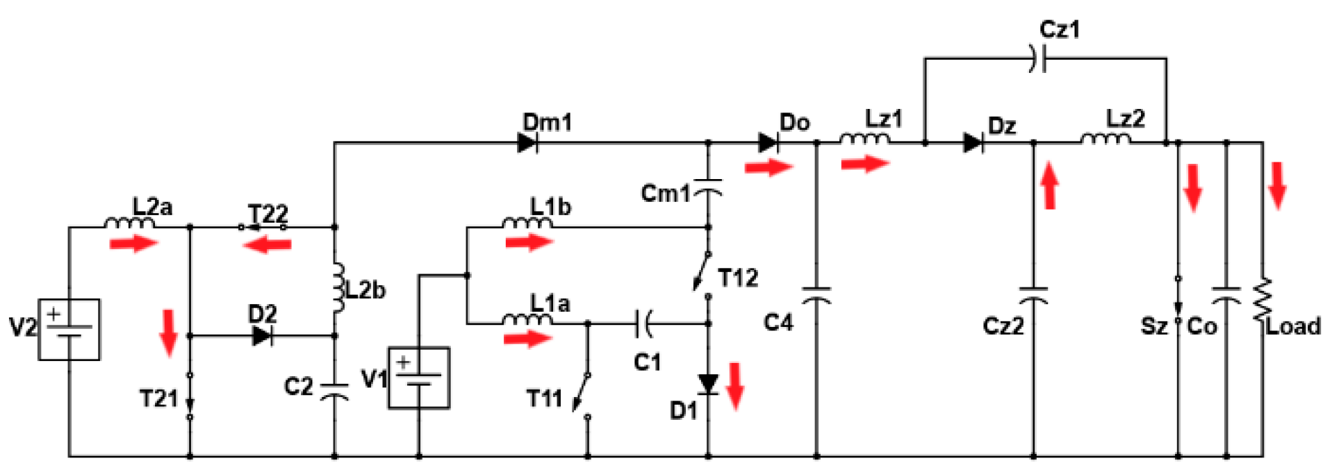
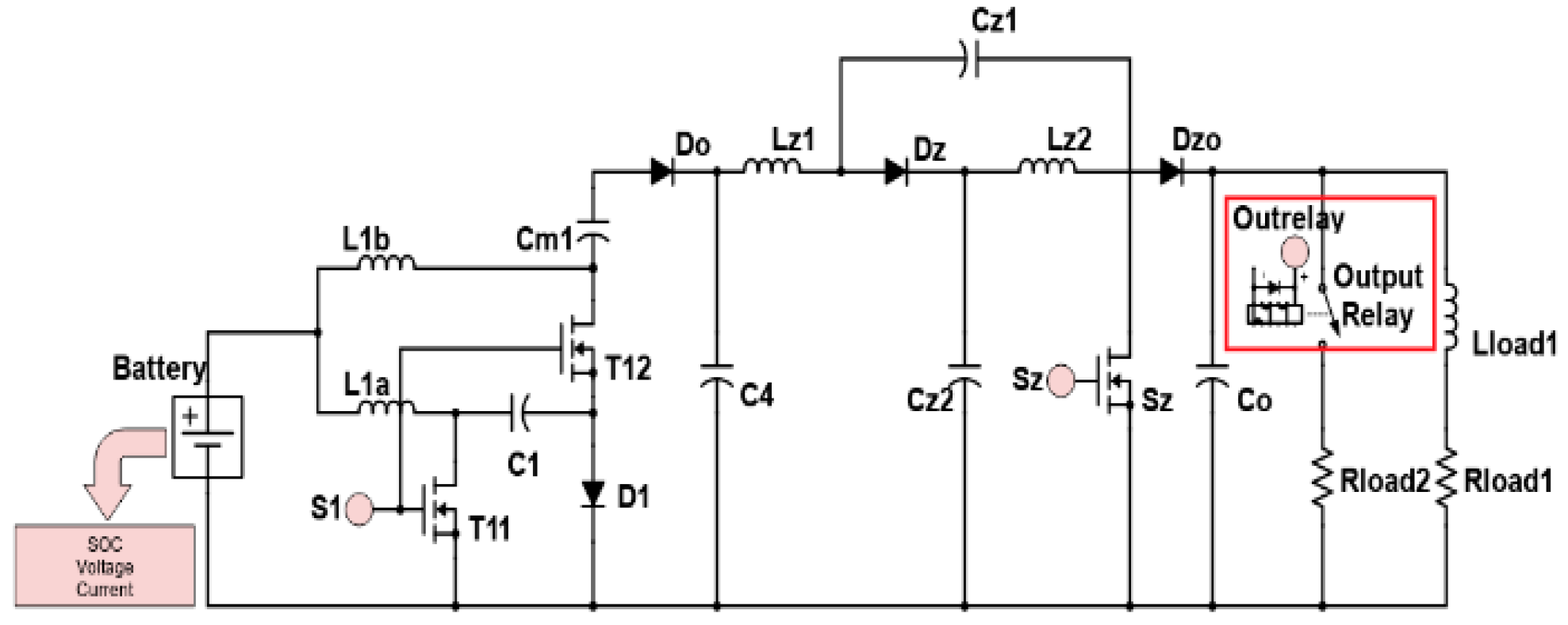
2. Proposed Multi-Port Converter with Quasi-Z-Source Network
2.1. Working Modes and Mathematical Expressions
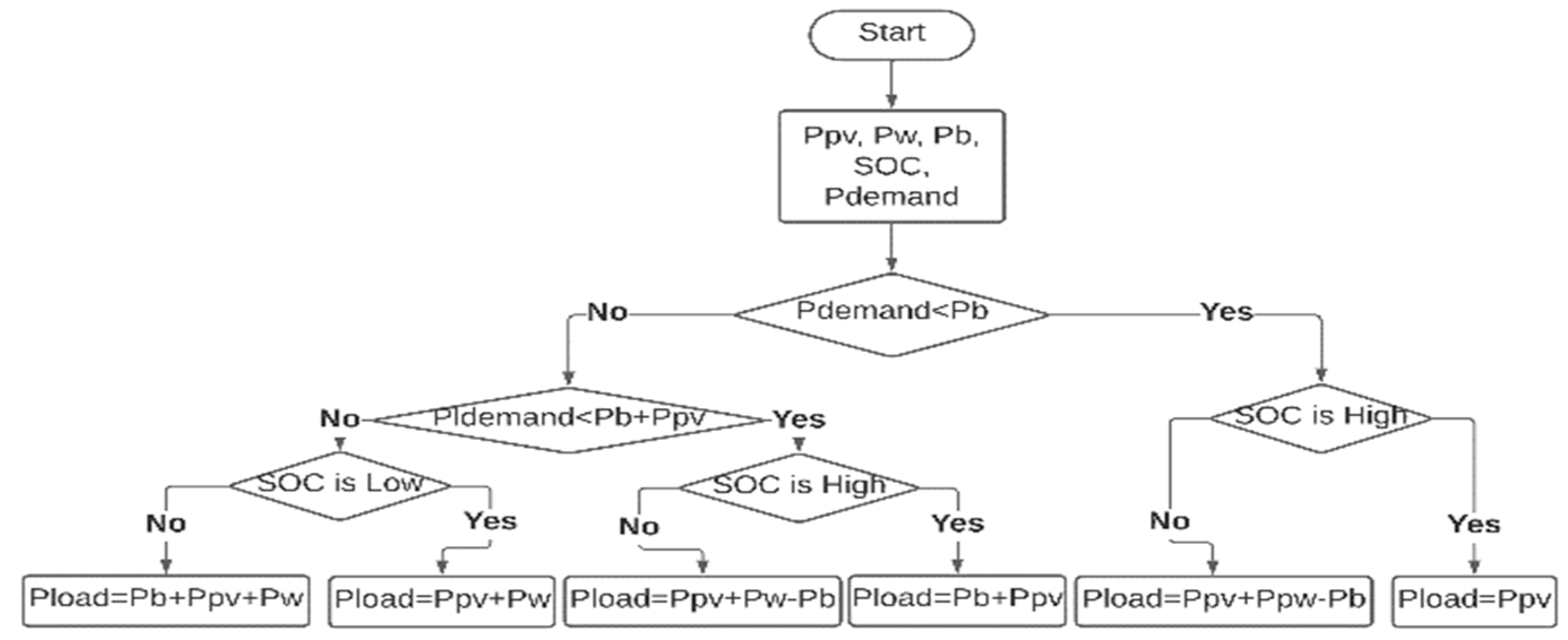
3. Proposed Energy Management Strategy
4. Simulation of the Proposed Control System
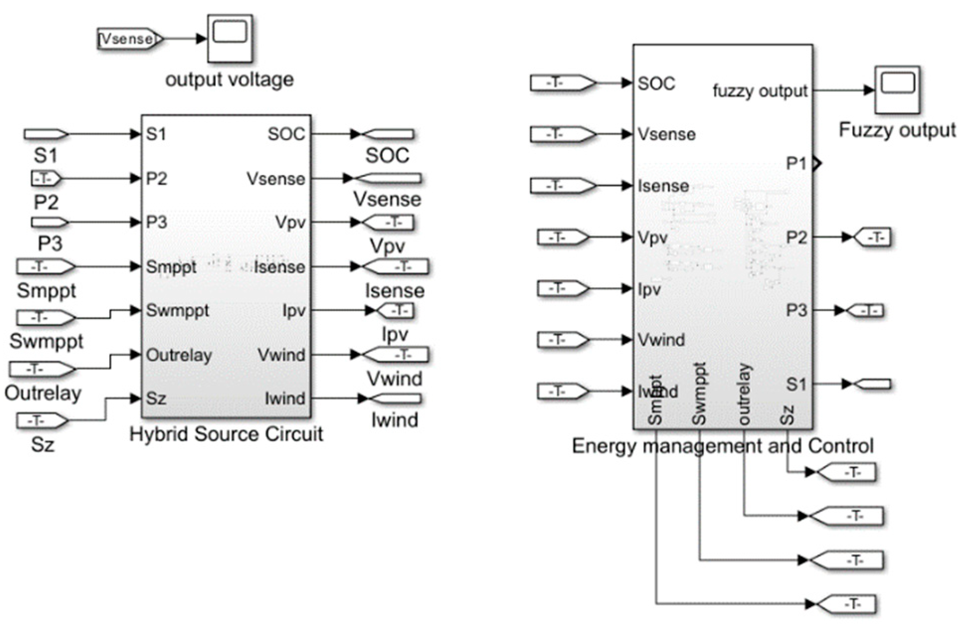
4.1. Simulink Model
4.2. Other Control Parameters
4.3. Simulation Results
5. Experimental Test
| Components | Values |
|---|---|
| L1a, L2a, L1b, L2b, L3a, L3b | 100 µH |
| C1, C3 | 47 µF |
| C2 | 470 µF |
| Cm1, Cm2 | 470 µF |
| Co | 680 µF |
| CPV, CWind | 470 µF |
| CZ1, CZ2 | 33 µF |
| LZ1, LZ2 | 100 µH |
| Load 1 | 440 ohm, 33 µH |
| Load 2 | 680 ohm |
5.1. Experimental Results
6. Discussion and Comparison
7. Conclusion
Appendix A
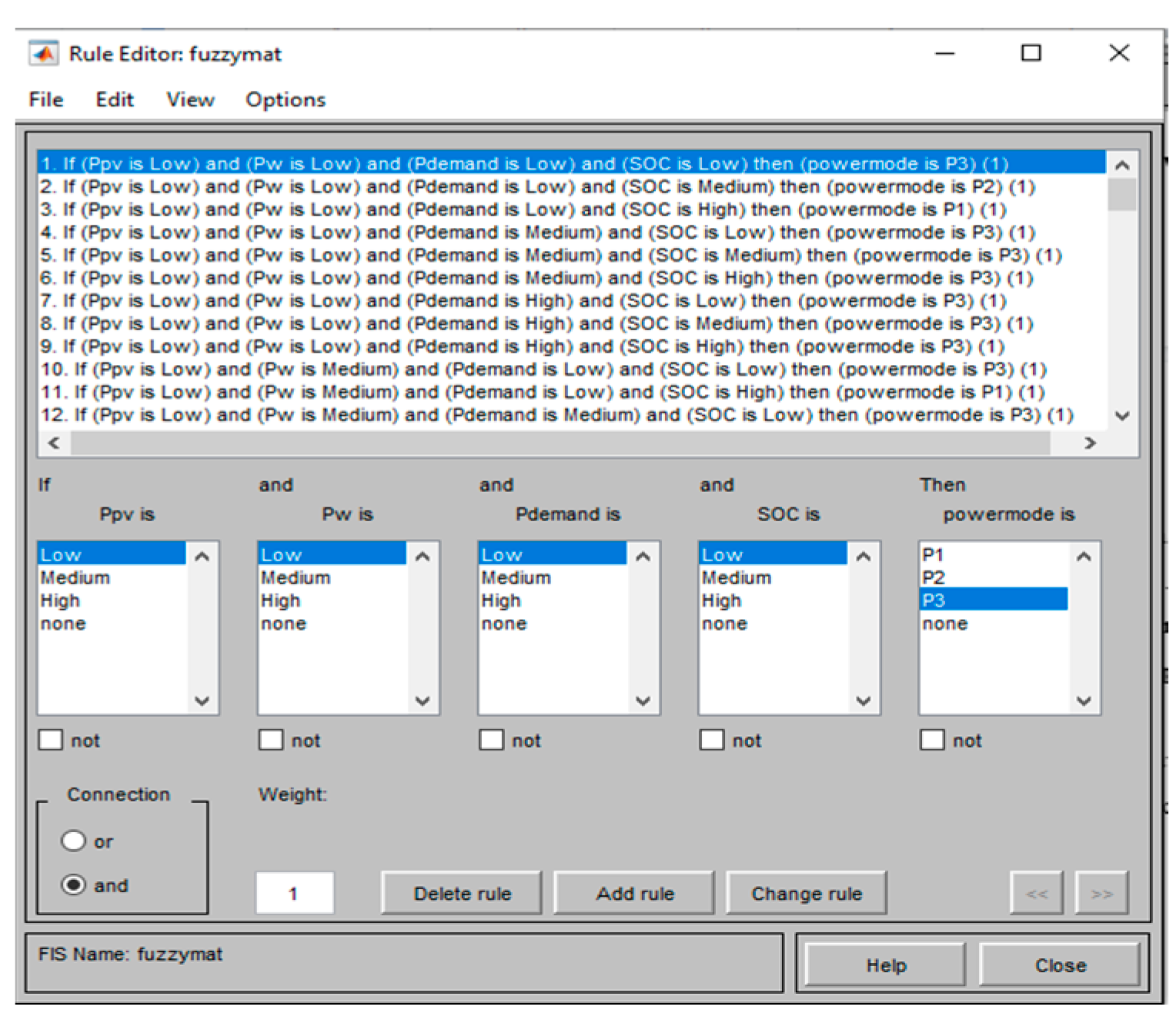
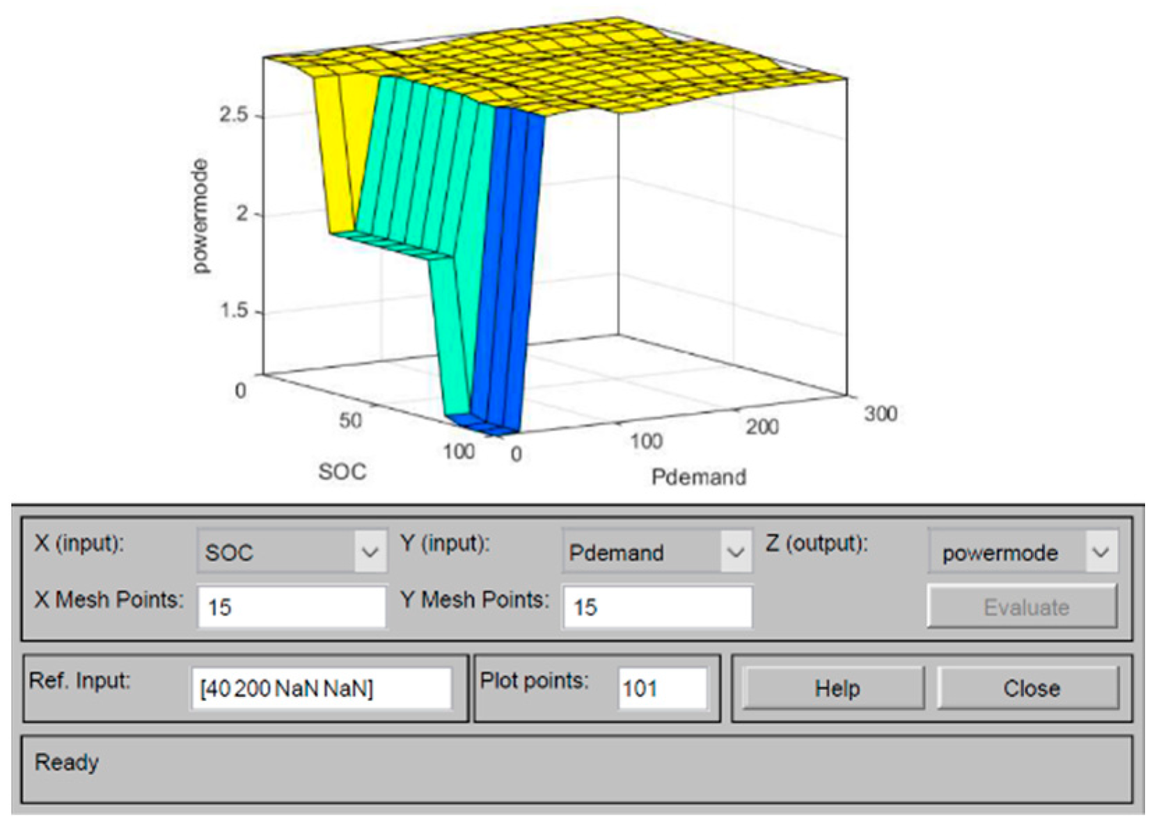
- If Ppv is low and Pwind is low and Pdemand is low and SOC is low then power mode is P3
- If Ppv is low and Pwind is low and Pdemand is low and SOC is medium the power mode is P2
- If Ppv is low and Pwind is low and Pdemand is low and SOC is high then the power mode is P1
- If Ppv is low and Pwind is low and Pdemand is medium and SOC is low then power mode is P3
- If Ppv is low and Pwind is low and Pdemand is medium and SOC is medium then power mode is P3
- If Ppv is low and Pwind is low and Pdemand is medium and SOC is high then power mode is P3
- If Ppv is low and Pwind is low and Pdemand is high and SOC is low then power mode is P3
- If Ppv is low and Pwind is low and Pdemand is high and SOC is medium then power mode is P3
- If Ppv is low and Pwind is low and Pdemand is high and SOC is high then power mode is P3
- If Ppv is low and Pwind is medium Pdemand is low and SOC is low then power mode is P3
- If Ppv is low and Pwind is medium Pdemand is low and SOC is medium then power mode is P2
- If Ppv is low and Pwind is medium Pdemand is low and SOC is high then power mode is P1
- If Ppv is low and Pwind is medium Pdemand is medium and SOC is low then power mode is P3
- If Ppv is low and Pwind is medium Pdemand is medium and SOC is medium then power mode is P3
- If Ppv is low and Pwind is medium Pdemand is medium and SOC is high then power mode is P3
- If Ppv is low and Pwind is medium Pdemand is high and SOC is low then power mode is P3
- If Ppv is low and Pwind is medium Pdemand is high and SOC is medium then power mode is P3
- If Ppv is low and Pwind is medium Pdemand is high and SOC is high then power mode is P3
- If Ppv is low and Pwind is high Pdemand is low and SOC is low then power mode is P3
- If Ppv is low and Pwind is high Pdemand is low and SOC is medium then power mode is P2
- If Ppv is low and Pwind is high Pdemand is low and SOC is high then power mode is P1
- If Ppv is low and Pwind is high Pdemand is medium and SOC is low then power mode is P3
- If Ppv is low and Pwind is high Pdemand is medium and SOC is medium then power mode is P3
- If Ppv is low and Pwind is high Pdemand is medium and SOC is high then power mode is P3
- If Ppv is low and Pwind is high Pdemand is high and SOC is low then power mode is P3
- If Ppv is low and Pwind is high Pdemand is high and SOC is medium then power mode is P3
- If Ppv is low and Pwind is high Pdemand is high and SOC is high then power mode is P3
- If Ppv is medium and Pwind is low and Pdemand is low and SOC is low then power mode is P3
- If Ppv is medium and Pwind is low and Pdemand is low and SOC is medium the power mode is P2
- If Ppv is medium and Pwind is low and Pdemand is low and SOC is high then the power mode is P1
- If Ppv is medium and Pwind is low and Pdemand is medium and SOC is low then power mode is P3
- If Ppv is medium and Pwind is low and Pdemand is medium and SOC is medium then power mode is P3
- If Ppv is medium and Pwind is low and Pdemand is medium and SOC is high then power mode is P3
- If Ppv is medium and Pwind is low and Pdemand is high and SOC is low then power mode is P3
- If Ppv is medium and Pwind is low and Pdemand is high and SOC is medium then power mode is P3
- If Ppv is medium and Pwind is low and Pdemand is high and SOC is high then power mode is P3
- If Ppv is medium and Pwind is medium Pdemand is low and SOC is low then power mode is P3
- If Ppv is medium and Pwind is medium Pdemand is low and SOC is medium then power mode is P2
- If Ppv is medium and Pwind is medium Pdemand is low and SOC is high then power mode is P1
- If Ppv is medium and Pwind is medium Pdemand is medium and SOC is low then power mode is P3
- If Ppv is medium and Pwind is medium Pdemand is medium and SOC is medium then the power mode is P3
- If Ppv is medium and Pwind is medium Pdemand is medium and SOC is high then power mode is P3
- If Ppv is medium and Pwind is medium Pdemand is high and SOC is low then power mode is P3
- If Ppv is medium and Pwind is medium Pdemand is high and SOC is medium then power mode is P3
- If Ppv is medium and Pwind is medium Pdemand is high and SOC is high then power mode is P3
- If Ppv is medium and Pwind is high Pdemand is low and SOC is low then power mode is P3
- If Ppv is medium and Pwind is high Pdemand is low and SOC is medium then power mode is P3
- If Ppv is medium and Pwind is high Pdemand is low and SOC is high then power mode is P1
- If Ppv is medium and Pwind is high Pdemand is medium and SOC is low then power mode is P3
- If Ppv is medium and Pwind is high Pdemand is medium and SOC is medium then power mode is P3
- If Ppv is medium and Pwind is high Pdemand is medium and SOC is high then power mode is P3
- If Ppv is medium and Pwind is high Pdemand is high and SOC is low then power mode is P3
- If Ppv is medium and Pwind is high Pdemand is high and SOC is medium then power mode is P3
- If Ppv is medium and Pwind is high Pdemand is high and SOC is high then power mode is P3
- If Ppv is high and Pwind is low and Pdemand is low and SOC is low then power mode is P2
- If Ppv is high and Pwind is low and Pdemand is low and SOC is medium the power mode is P2
- If Ppv is high and Pwind is low and Pdemand is low and SOC is high then the power mode is P1
- If Ppv is high and Pwind is low and Pdemand is medium and SOC is low then power mode is P3
- If Ppv is high and Pwind is low and Pdemand is medium and SOC is medium then power mode is P3
- If Ppv is high and Pwind is low and Pdemand is medium and SOC is high then power mode is P2
- If Ppv is high and Pwind is low and Pdemand is high and SOC is low then power mode is P3
- If Ppv is high and Pwind is low and Pdemand is high and SOC is medium then power mode is P3
- If Ppv is high and Pwind is low and Pdemand is high and SOC is high then power mode is P3
- If Ppv is high and Pwind is medium Pdemand is low and SOC is low then power mode is P2
- If Ppv is high and Pwind is medium Pdemand is low and SOC is medium then power mode is P2
- If Ppv is high and Pwind is medium Pdemand is low and SOC is high then power mode is P1
- If Ppv is high and Pwind is medium Pdemand is medium and SOC is low then power mode is P3
- If Ppv is high and Pwind is medium Pdemand is medium and SOC is medium then power mode is P3
- If Ppv is high and Pwind is medium Pdemand is medium and SOC is high then power mode is P2
- If Ppv is high and Pwind is medium Pdemand is high and SOC is low then power mode is P3
- If Ppv is high and Pwind is medium Pdemand is high and SOC is medium then power mode is P3
- If Ppv is high and Pwind is medium Pdemand is high and SOC is high then power mode is P3
- If Ppv is high and Pwind is high Pdemand is low and SOC is low then power mode is P2
- If Ppv is high and Pwind is high Pdemand is low and SOC is medium then power mode is P2
- If Ppv is high and Pwind is high Pdemand is low and SOC is high then power mode is P1
- If Ppv is high and Pwind is high Pdemand is medium and SOC is low then power mode is P3
- If Ppv is high and Pwind is high Pdemand is medium and SOC is medium then power mode is P3
- If Ppv is high and Pwind is high Pdemand is medium and SOC is high then power mode is P2
- If Ppv is high and Pwind is high Pdemand is high and SOC is low then power mode is P3
- If Ppv is high and Pwind is high Pdemand is high and SOC is medium then power mode is P3
- If Ppv is high and Pwind is high Pdemand is high and SOC is high then power mode is P3
References
- Yan Li; Dongsheng Yang; Xinbo Ruan A Systematic Method for Generating Multiple-Input DC/DC Converters. In Proceedings of the 2008 IEEE Vehicle Power and Propulsion Conference; IEEE, September 2008; pp. 1–6.
- Nejabatkhah, F.; Danyali, S.; Hosseini, S.H.; Sabahi, M.; Niapour, S.M. Modeling and Control of a New Three-Input Dc-Dc Boost Converter for Hybrid PV/FC/Battery Power System. IEEE Trans Power Electron 2012, 27, 2309–2324. [CrossRef]
- Argentini, S.; Pietroni, I.; Mastrantonio, G.; Viola, A.; Zilitinchevich, S. Characteristics of The. 2006, 51, 1–14.
- Dobbs, B.G.; Chapman, P.L. A Multiple-Input DC-DC Converter Topology. IEEE Power Electronics Letters 2003, 1, 6–9. [CrossRef]
- Karthikeyan, V.; Gupta, R. Multiple-Input Configuration of Isolated Bidirectional DC–DC Converter for Power Flow Control in Combinational Battery Storage. IEEE Trans Industr Inform 2018, 14, 2–11. [CrossRef]
- Ahrabi, R.R.; Ardi, H.; Elmi, M.; Ajami, A. A Novel Step-Up Multiinput DC–DC Converter for Hybrid Electric Vehicles Application. IEEE Trans Power Electron 2017, 32, 3549–3561. [CrossRef]
- Dezhbord, M.; Mohseni, P.; Hosseini, S.H.; Mirabbasi, D.; Islam, Md.R. A High Step-Up Three-Port DC–DC Converter With Reduced Voltage Stress for Hybrid Energy Systems. IEEE Journal of Emerging and Selected Topics in Industrial Electronics 2022, 3, 998–1009. [CrossRef]
- Nazih, Y.; Abdel-Moneim, M.G.; Aboushady, A.A.; Abdel-Khalik, A.S.; Hamad, M.S. A Ring-Connected Dual Active Bridge Based DC-DC Multiport Converter for EV Fast-Charging Stations. IEEE Access 2022, 10, 52052–52066. [CrossRef]
- Jalilzadeh, T.; Rostami, N.; Babaei, E.; Hosseini, S.H. Bidirectional Multi-port Dc–Dc Converter with Low Voltage Stress on Switches and Diodes. IET Power Electronics 2020, 13, 1593–1604. [CrossRef]
- Ninma Jiya, I.; Van Khang, H.; Kishor, N.; Ciric, R.M. Novel Family of High-Gain Nonisolated Multiport Converters With Bipolar Symmetric Outputs for DC Microgrids. IEEE Trans Power Electron 2022, 37, 12151–12166. [CrossRef]
- Varesi, K.; Hosseini, S.H.; Sabahi, M.; Babaei, E. Modular Non-Isolated Multi-Input High Step-up Dc-Dc Converter with Reduced Normalised Voltage Stress and Component Count. IET Power Electronics 2018, 11, 1092–1100. [CrossRef]
- Varesi, K.; Hosseini, S.H.; Sabahi, M.; Babaei, E. A Multi-Port High Step-Up DC-DC Converter with Reduced Normalized Voltage Stress on Switches/Diodes. 9th Annual International Power Electronics, Drive Systems, and Technologies Conference, PEDSTC 2018 2018, 2018-Janua, 1–6. [CrossRef]
- Fang Zheng Peng Z-Source Inverter. IEEE Trans Ind Appl 2003, 39, 504–510. [CrossRef]
- Tang, Y.; Xie, S.; Zhang, C. An Improved $Z$-Source Inverter. IEEE Trans Power Electron 2011, 26, 3865–3868. [CrossRef]
- Shen, H.; Zhang, B.; Qiu, D.; Zhou, L. A Common Grounded Z-Source DC–DC Converter With High Voltage Gain. IEEE Transactions on Industrial Electronics 2016, 63, 2925–2935. [CrossRef]
- Anderson, J.; Peng, F.Z. Four Quasi-Z-Source Inverters. In Proceedings of the 2008 IEEE Power Electronics Specialists Conference; IEEE, June 2008; pp. 2743–2749.
- Hosseini, S.M.; Ghazi, R.; Nikbahar, A.; Eydi, M. A New Enhanced-boost Switched-capacitor Quasi Z-source Network. IET Power Electronics 2021, 14, 412–421. [CrossRef]
- Torki Harchegani, A.; Asghari, A.; Jazaeri, M. A New Soft-switching Multi-input Quasi-Z-source Converter for Hybrid Sources Systems. IET Renewable Power Generation 2021, 15, 1451–1468. [CrossRef]
- Biasini, R.; Onori, S.; Rizzoni, G. A Near-Optimal Rule-Based Energy Management Strategy for Medium Duty Hybrid Truck. International Journal of Powertrains 2013, 2, 232. [CrossRef]
- Petrović, D.J.; Lazić, M.M.; Lazić, B.V.J.; Blanuša, B.D.; Aleksić, S.O. Hybrid Power Supply System with Fuzzy Logic Controller: Power Control Algorithm, Main Properties, and Applications. Journal of Modern Power Systems and Clean Energy 2021, 1–9.
- Ganguly, P.; Kalam, A.; Zayegh, A. Fuzzy Logic-Based Energy Management System of Stand-Alone Renewable Energy System for a Remote Area Power System. Australian Journal of Electrical and Electronics Engineering 2019, 16, 21–32. [CrossRef]
- Koulali, M.; Mankour, M.; Negadi, K.; Mezouar, A. Energy Management of Hybrid Power System PV Wind and Battery Based Three Level Converter. TECNICA ITALIANA-Italian Journal of Engineering Science 2019, 63, 297–304. [CrossRef]
- Baset, D.A.-E.; Rezk, H.; Hamada, M. Fuzzy Logic Control Based Energy Management Strategy for Renewable Energy System. In Proceedings of the 2020 International Youth Conference on Radio Electronics, Electrical and Power Engineering (REEPE); IEEE, March 2020; pp. 1–5.
- Teo, T.T.; Logenthiran, T.; Woo, W.L.; Abidi, K.; John, T.; Wade, N.S.; Greenwood, D.M.; Patsios, C.; Taylor, P.C. Optimization of Fuzzy Energy-Management System for Grid-Connected Microgrid Using NSGA-II. IEEE Trans Cybern 2021, 51, 5375–5386. [CrossRef]
- Zhang, Z.; Guan, C.; Liu, Z. Real-Time Optimization Energy Management Strategy for Fuel Cell Hybrid Ships Considering Power Sources Degradation. IEEE Access 2020, 8, 87046–87059. [CrossRef]
- Wang, T.; Li, Q.; Wang, X.; Qiu, Y.; Liu, M.; Meng, X.; Li, J.; Chen, W. An Optimized Energy Management Strategy for Fuel Cell Hybrid Power System Based on Maximum Efficiency Range Identification. J Power Sources 2020, 445, 227333. [CrossRef]
- Namwook Kim; Sukwon Cha; Huei Peng Optimal Control of Hybrid Electric Vehicles Based on Pontryagin’s Minimum Principle. IEEE Transactions on Control Systems Technology 2011, 19, 1279–1287. [CrossRef]
- Yu, J.; Dou, C.; Li, X. MAS-Based Energy Management Strategies for a Hybrid Energy Generation System. IEEE Transactions on Industrial Electronics 2016, 63, 3756–3764. [CrossRef]
- Garcia, P.; Garcia, C.A.; Fernandez, L.M.; Llorens, F.; Jurado, F. ANFIS-Based Control of a Grid-Connected Hybrid System Integrating Renewable Energies, Hydrogen and Batteries. IEEE Trans Industr Inform 2014, 10, 1107–1117. [CrossRef]
- Li, Q.; Wang, T.; Dai, C.; Chen, W.; Ma, L. Power Management Strategy Based on Adaptive Droop Control for a Fuel Cell-Battery-Supercapacitor Hybrid Tramway. IEEE Trans Veh Technol 2018, 67, 5658–5670. [CrossRef]
- Zhang, S.; Xiong, R.; Sun, F. Model Predictive Control for Power Management in a Plug-in Hybrid Electric Vehicle with a Hybrid Energy Storage System. Appl Energy 2017, 185, 1654–1662. [CrossRef]
- Suthar, S.; Pindoriya, N.M. Energy Management Platform for Integrated Battery-Based Energy Storage – Solar PV System: A Case Study. IET Energy Systems Integration 2020, 2, 373–381. [CrossRef]
- Ghosh, S.K.; Roy, T.K.; Pramanik, M.A.H.; Mahmud, M.A. A Nonlinear Double-integral Sliding Mode Controller Design for Hybrid Energy Storage Systems and Solar Photovoltaic Units to Enhance the Power Management in DC Microgrids. IET Generation, Transmission & Distribution 2022, 16, 2228–2241. [CrossRef]


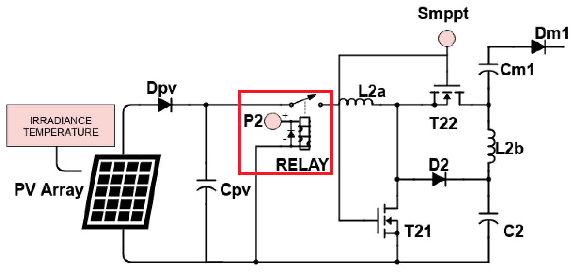
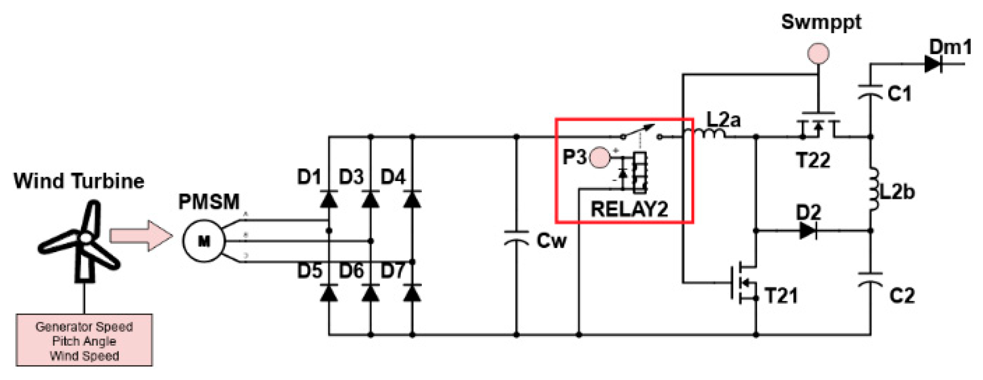
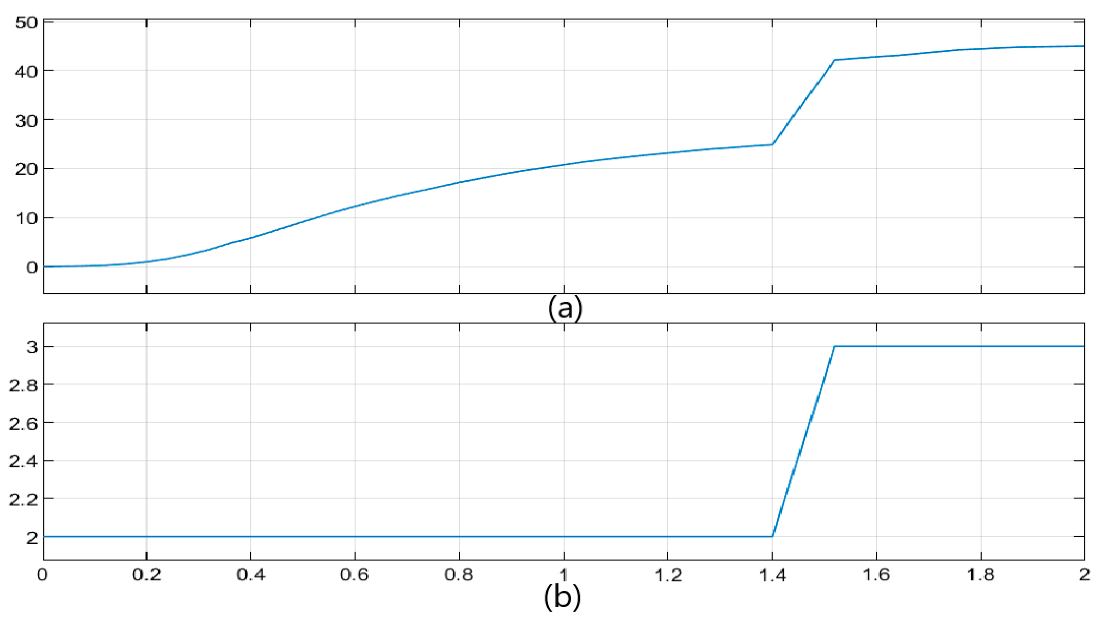
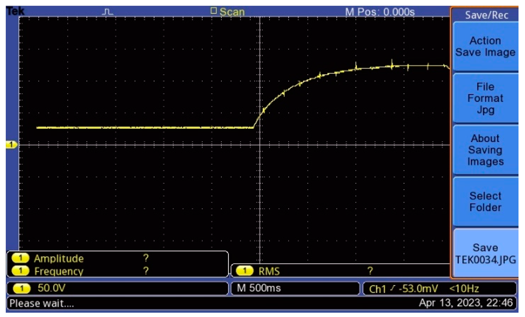

| Open-circuit voltage VOC (V) | 22.77 |
| Short-circuit current ISC (A) | 5.86 |
| Voltage at Maximum Power Point Vmp (V) | 18.3 |
| Current at Maximum Power Point Imp (A) | 5.5 |
| Reference | Adv. / Disadv. | Response Time | Complexity | No. of Inputs |
|---|---|---|---|---|
| [25] | Fuel economy is good, system durability is high, Complex system, limited application area | - | High | 3 inputs (Fuel cell, battery, Super Capacitor) |
| [27] | Reasonable assumptions, Complex system | + | High | |
| [28] | High decision-making time, Complex system | - | High | 3 inputs (PV, Wind turbine, Battery) |
| [29] | Hybrid sources, Needs datasets | + | Medium | 5 inputs (Grid, PV, Wind turbine, Fuel Cell, Battery) |
| [31] | Can predict future, large-scale operations are difficult, Needs datasets | + | Medium | 2 inputs (LTO; Li-Ti-O battery, NCM; Ni-Co-Mn battery) |
| Proposed System | No mathematical algorithm, fuzzy rules, can adapt high number of sources | + | Low | N numbered (any type of source including renewable sources) |
Disclaimer/Publisher’s Note: The statements, opinions and data contained in all publications are solely those of the individual author(s) and contributor(s) and not of MDPI and/or the editor(s). MDPI and/or the editor(s) disclaim responsibility for any injury to people or property resulting from any ideas, methods, instructions or products referred to in the content. |
© 2023 by the authors. Licensee MDPI, Basel, Switzerland. This article is an open access article distributed under the terms and conditions of the Creative Commons Attribution (CC BY) license (http://creativecommons.org/licenses/by/4.0/).


