Preprint
Review

A Review of Combined Heat and Power (CHP)

Altmetrics

Downloads

402

Views

99

Comments

0

This version is not peer-reviewed

Submitted:

26 April 2023

Posted:

27 April 2023

You are already at the latest version

Alerts
Abstract
The combined heat and power system is based on the principle of "cascade utilization of thermal energy" for system integration and optimization. The rational utilization of energy, as well as the rational arrangement of energy flow and the process optimization combination of the overall system are taken into account in order to achieve multifunctional goals in the field of thermal engineering. The present paper presents a detailed assessment of combined heat and power systems from above standpoints. This article is divided into two parts “CHP based on thermo-dynamic cycles” and “CHP based on non-thermodynamic cycles”. Each part is then classified based on power subsystem energy consumption efficiency (high or low), including Rankine cycle, ORC, Stirling cycle, gas turbine, reciprocating engine, PVT and fuel cell. The present paper also helps identify the research gaps in this area and provides direction on future studies on combined heat and power systems.
Keywords: 
Subject: Engineering  -   Electrical and Electronic Engineering

1. Introduction

In daily life and industrial production, the required form of energy utilization is frequently not only limited to electricity or mechanical work, but also a large amount of heat demand at various temperatures, such as steam for various processes, heat for heating, domestic hot water, and so on. Under some technological conditions, the power system or heating system alone will not be able to significantly improve performance, because traditional power generation or heating sub-production systems are extremely inefficient in terms of energy conversion. For the power generation system, the heat engine can only convert a portion of the combustion heat (i.e. the heat transferred from the high temperature heat source to the heat engine) released from the combustion of fossil fuels into electricity, and the remainder is transferred to the low temperature heat source (mostly the environment), implying that the power system converts approximately one-third of the combustion heat released from the fuel into electricity, and the other is wasted. Although the boiler converts 70-90% of the heat from fuel combustion into useful thermal energy (steam or hot water) for the user in conventional heating systems, the available energy in the high-temperature section when the fuel used to produce heat is burned to produce combustion products is not fully utilized and instead goes directly to produce steam or hot water at lower temperatures, resulting in a large destruction of available energy.
The combined power and heat supply system is a system integration means that is based on the principle of "cascade utilization of thermal energy," which is optimized within the system and forms an integrated system by organically integrating the power and heat conversion process and the heat supply process to realize various functions such as power generation and heat supply, thus significantly improving the energy utilization effect. Co-generation, often known as combined heat and power, is the output of mechanical work or electrical energy from a heat engine while producing heat for industrial and home consumption. Co-generation and combined heat and power are other names for it. Its purpose is to reuse the heat that was created when materials were put to use in different heat engines. While the majority of heat users do not require high temperatures, the real manufacturing process system frequently has a particular demand for both electricity and heat, which can frequently be satisfied by the waste heat of the heat engine with the output power. In accordance with the high efficient utilization of energy, the high temperature component outputs work and the low temperature section supplies heat in this manner. In order to simultaneously accomplish multiple functional goals in the fields of power and heat, the combined power and heat supply system is based on the principle of integrated energy use in a stepwise manner for system integration and optimization, taking into account the rational use of energy in the input system and the rational arrangement of energy flow and process optimization combination of the overall system.
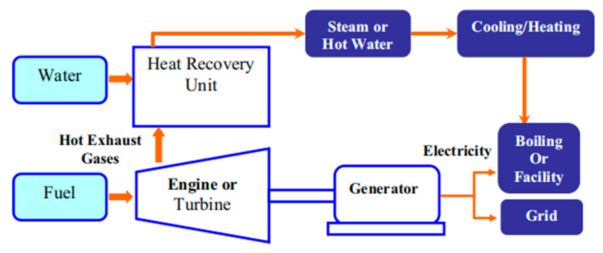
CHP technologies are classified into two types: those that are based on thermodynamic cycle technologies and those that are not. External combustion cycles and internal combustion cycles are included in the first classifications. Figure 1 depicts the logical notion block diagram of this paper.

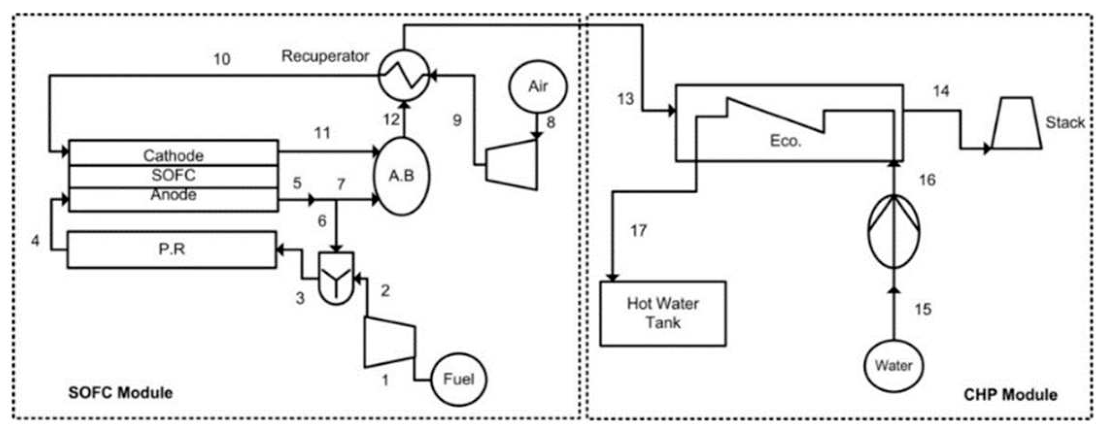
2. CHP based on thermodynamic cycles

An external combustion thermodynamic cycle uses fossil fuel combustion to heat a circulating mass and converts thermal energy into mechanical energy in a turbine. Besides fossil fuels solar energy, biomass, and atomic energy can also serve as a heat source. The development of CHP based on external combustion cycles, including Rankine cycle, ORC and Stirling cycle, are introduced as follows.

2.1. CHP based on Rankine cycles

Most of coal-fired power plants are based on the Rankine cycle with steam as the working fluid. The Rankine cycle is made up of four components: an isentropic adiabatic pump, a heat exchanger that aids in the vaporization process, a turbine that operates under perfect conditions, and a condenser with no pressure loss. The Rankine cycle, which has an unlimited contact surface for heat transmission, may convert heat energy into mechanical energy, making it the simplest steam power cycle known[1]. CHP applications based on the boiler and steam turbine (Rankine cycle) have received a great deal of attention throughout the years.

2.1.1. Coal-fired co-generation system

The coal-fired co-generation unit has the characteristics of high efficiency and low pollution, but its production mode of ‘power by heat’ limits its power load regulation ability[2,3]. In a typical coal-fired co-generation unit in China, the waste heat from exhaust steam accounts for more than 30% of the total energy consumption. Making good use of it can not only enhance the peak load capacity of the system, but also improve the heating capacity of the system, save the consumption of heating fuel, and help reduce the carbon dioxide emission[4]. At present, the heat generation technologies mainly include high back-pressure heating, heat pump waste heat recovery, zero-output modification of low-pressure turbine.
  • HIGH BACK-PRESSURE HEATING
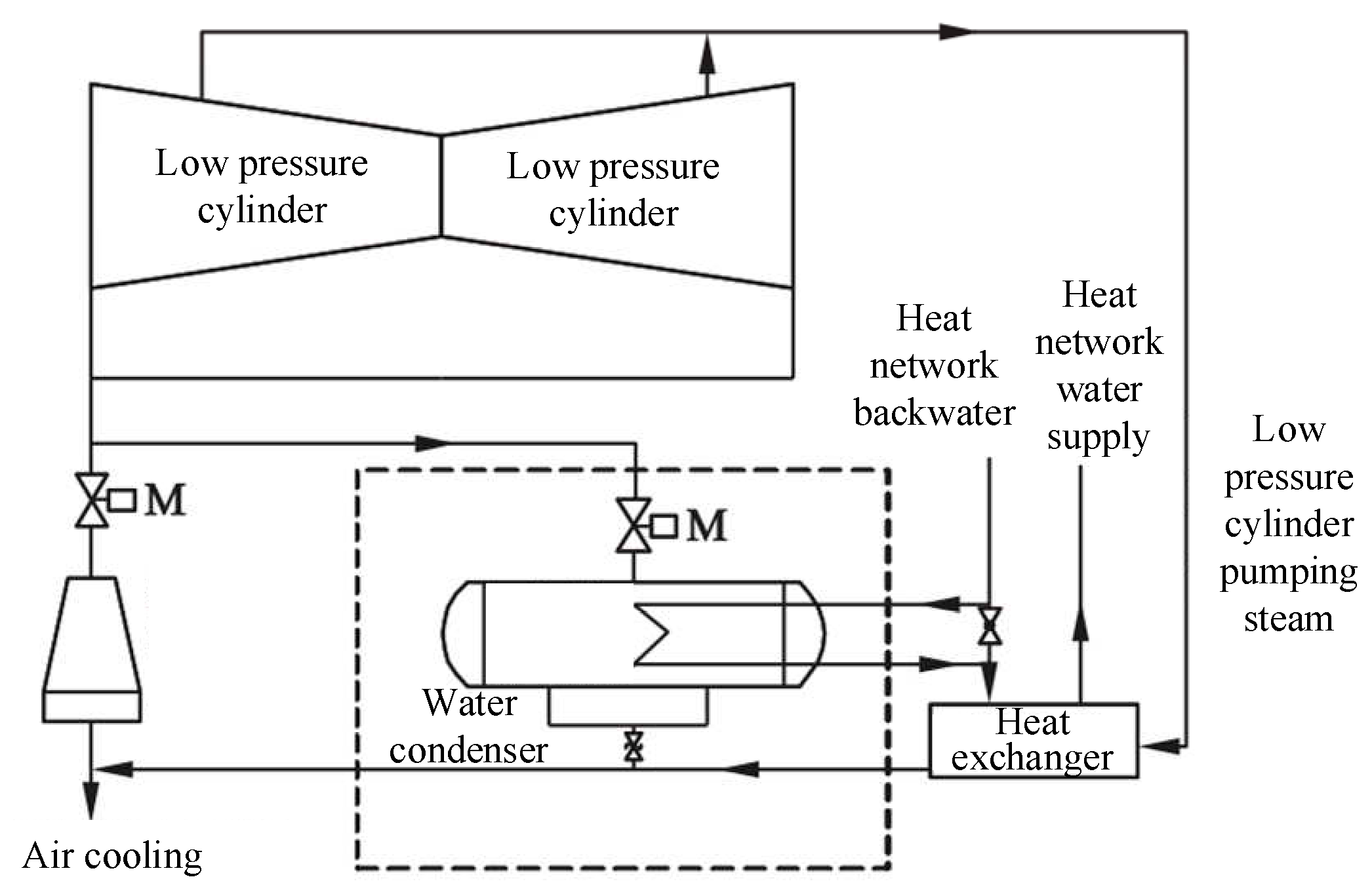
At present, the modification of high back-pressure heating is mainly based on the air-cooling unit. The principle is to increase the operating back pressure of the unit, so as to increase the exhaust temperature of the steam turbine, and directly use the exhaust steam of the steam turbine to heat the circulating water of a heating network. This method can effectively utilize the waste heat of steam turbine exhaust, avoid the loss of cold source, improve the thermal efficiency of the unit, and realize energy saving and emission reduction comparing with individual power plant and heating plant. At the same time, the heating capacity and heating area of the system can be increased without increasing new equipment. Wang et al.[5] removed the original rotor blades at the last stage and the second stage, and installed false blade roots. The final stage and the second stage partitions were removed and replaced with guide rings. The coal consumption of power supply decreased from 289.48g/ (kW·h) to 151.04g/ (kW·h), and the thermal/electricity ratio increased from 41.31% to 183.74%. Tian et al.[6] developed a direct high back pressure circulating water heating transformation project, according to the characteristics of a 330MW air cooling unit, which does not change the status of the air cooling island. 1# steam turbine generator unit is added with a water-cooled condenser. During the heating period, the scheme recovers the waste heat of steam turbine exhaust for primary heating by increasing the back pressure of the steam turbine, and uses the unit extraction for secondary heating to improve the heating and heating capacity of the unit. The principle of the transformation scheme is shown in Figure 2. The heating temperature of the circulating water of the heat network increased to 68oC, and the annual heat supply increased.
Zhang et al.[7] adopted the high back pressure reform scheme of circulating water to change the flow rate of circulating water, the return water temperature and the exhaust steam flow of the unit. During the heating period, the average electrical load was 250 MW and the average heating capacity was 1.30 TJ/h. The average coal consumption of the unit was reduced by 32.10g/ (kW·h). Gong et al.[8] built a model and verified the accuracy of the model using EBSILON software. According to the thermal model, the performance of the unit after the modification of high back pressure heating was analyzed. The thermal/electric ratio reached 200%, which effectively alleviated the contradiction of using more heat and less electricity, and improved the peak regulating capacity of the unit.
Through the research of the above literatures, it can be found that the applications of high back pressure heating modification are as follows: the scheme is suitable for the heating system in buildings that the return water temperature of the heat network is low and the actual heating load should be close to the maximum heating load. However, the drawback of it is the low efficiency of power generation during non-heating situations. As a result, when determining working conditions, the optimal solution should be determined based on the corresponding back pressure range of the wet-cooled and air-cooled units under heating and non-heating conditions, taking into account pumping capacity, condenser inlet and outlet water temperature, and discharge temperature.
  • HEAT PUMP WASTE HEAT RECOVERY
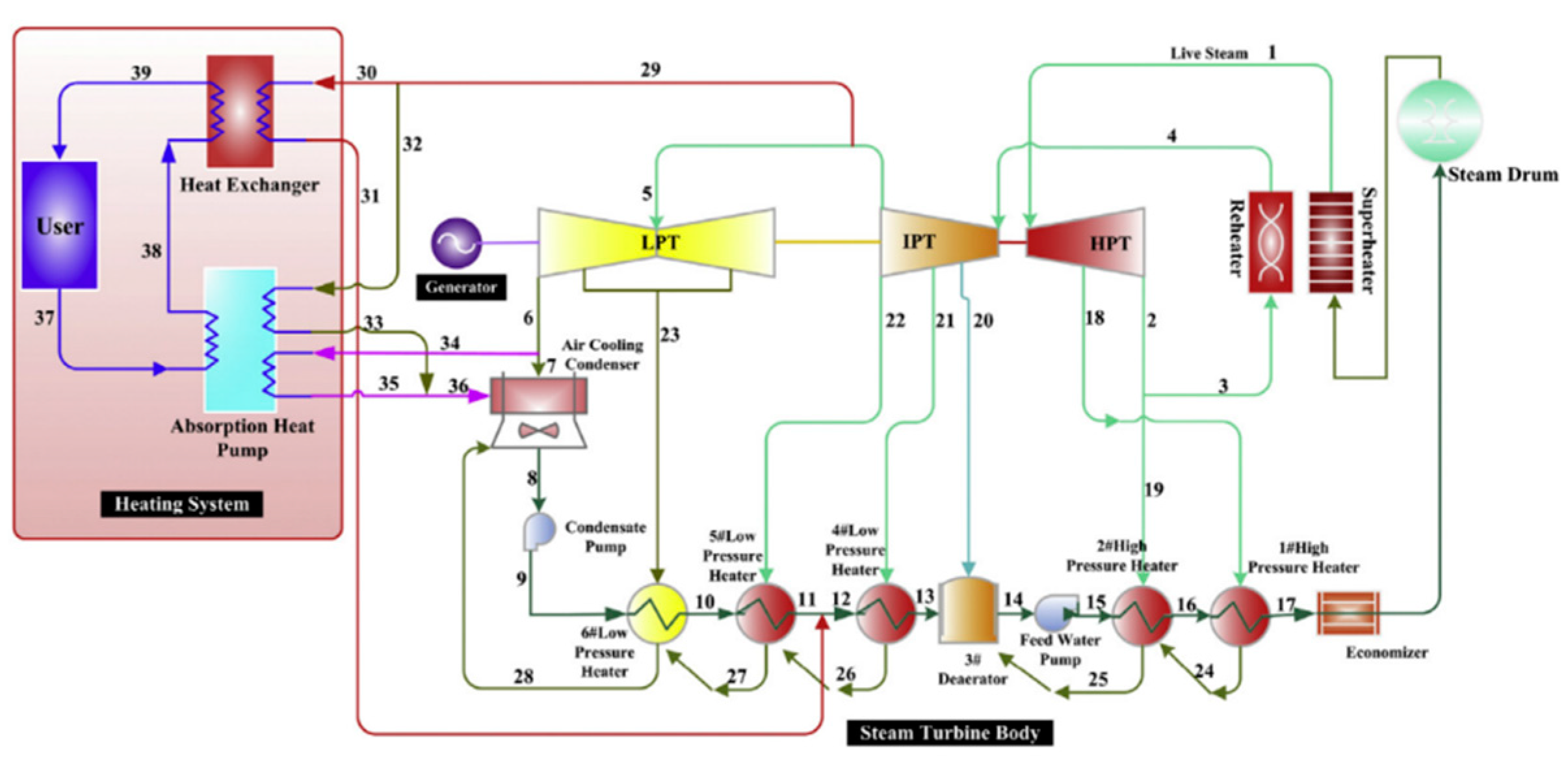
Absorption heat pump (AHP) uses thermal energy to drive the working medium to flow in the cycle. The plant uses the steam extracted from the steam turbine to drive the heat pump to absorb the heat from the exhaust steam and transfer the heat to the urban heat network. The heat supply of the AHP is the sum of the heat absorbed from the steam and the driving heat. Some researchers have proposed that AHP can be used to heat the water supply of a primary heating network using exhaust steam[9]. Some scholars have studied the thermodynamic and parameter characteristics of AHP system in co-generation unit. Figure 3[10] shows the schematic diagram of 135MW absorption heat pump coal-fired cogeneration power plant. The steam parameter is 13.24 MPa/535oC/535oC, and the final feedwater temperature is about 243.4oC. It uses three low-pressure FWHs, two high-pressure FWHs and one deaerator. First, the absorption heat pump system is used to heat the return water of the heating network and recover part of the waste heat. The use of absorption heat pump system saves the high parameter steam that should be extracted for heating, so that the high parameter steam can return to the turbine for further work, thus improving the economic operation of the unit.
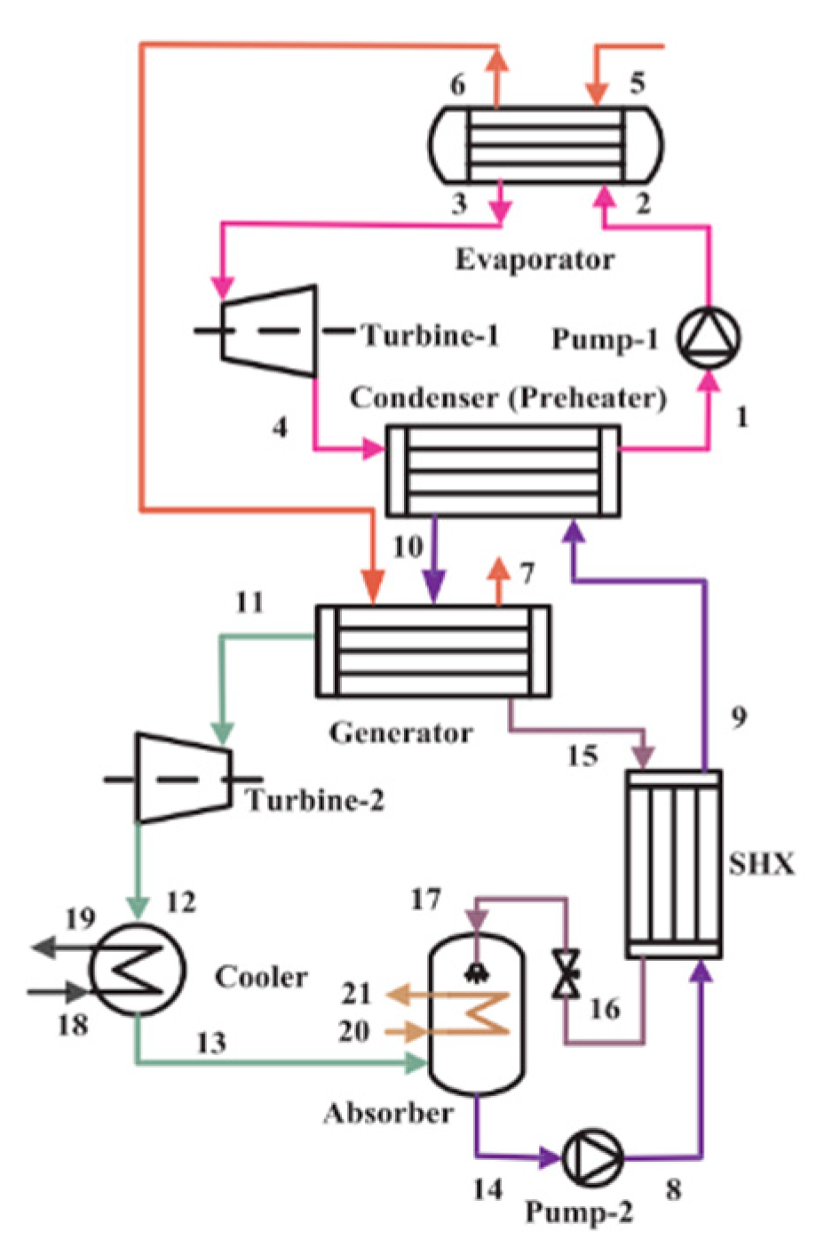
Sun et al.[11] presented a novel waste heat district heating system with CHP based on ejector heat exchangers and AHP to decrease heating energy consumption of existing CHP systems by recovering waste heat of exhausted steam from a steam turbine, which could also increase heat transmission capacity of the primary heating network (PHN) by decreasing temperature of the return water of existing PHN. Compared to conventional district heating systems with CHP, the new system can decrease consumption of steam extracted from a steam turbine by 41.4% and increase heat transmission capacity of the existing PHN by 66.7% without changing the flow rate of circulating water. Ommen[12] identified and compared five generic configurations of heat pumps in district heating systems. The results showed that in terms of system performance and cost of fuel one or two configurations were superior for all of the considered cases. When considering a case where the heat pump was located at a CHP plant, a configuration that increased the DH return temperature proposed the lowest operation cost, as low as 12 EUR MWh-1 for a 90-40oC district heating network. Liang[13] proposed an electricity-cooling co-generation system based on coupling of a steam Rankine cycle and an absorption refrigeration system to recover the waste heat of marine engine to meet the electricity and cooling demand aboard. The equivalent electricity output of the waste heat recovery system is 5223 kW, accounting for 7.61% of the rated power output of the marine engine. The schematic diagram of the novel ECCS is shown in Figure 4.
Cho et al.[14] presented a design study of a CHP system integrated with a heat pump. CHP with a heat pump can be effectively used to reduce energy cost in cold climate zones.
Another method to recover the waste heat of exhaust steam is to use absorption heat exchanger (AHE) at the heat transfer subtraction, reduce the return water temperature of the primary heating network, and cool the exhaust steam with low temperature return water. Sun et al.[15] invented a new exchange named AHE at the thermal substation to increase the heating capacity of current heating pipes significantly. Wang et al.[16] adopted an entransy analysis as an optimization method for the heat exchange process. The AHE model is simplified and the mathematical representations of each entransy dissipation part are provided. The optimal flow distribution principle is obtained by calculating the minimum value of the total entransy dissipation. Xie[17] introduced a new system for long-distance heat transportation which used two types of AHE. Using this system, industrial waste heat at 65-70oC can be recovered and transported through long-distance pipelines. Both of AHP and AHE cycles deliver energy from low-temperature heat source to high-temperature heat source through working fluids, such as H2O-LiBr and NH3-H2O[18,19].
Based on above literatures reviews, it can be concluded that the AHE waste heat recovery is suitable for following situations: It can be used in thermal power plant waste steam recovery heating. And it is suitable for high temperature of cooling circulating water and high pressure of pumping steam. AHE differs from the high back pressure heating modification, which has a high power generation efficiency and high heating temperatures throughout the non-heating condition. However, this approach necessitates great air tightness, and any minor air loss into the device would degrade performance. As a result, its system is more intricate and expensive.
  • ZERO-OUTPUT MODIFICATION OF LOW-PRESSURE TURBINE
The zero-output modification of low-pressure turbine can be divided into cutting out the inlet steam of low-pressure turbine and optical shaft modification. The principle of cutting out the low-pressure turbine is to replace the connecting pipe between medium-pressure cylinder and low-pressure cylinder with a new connecting pipe. The new connecting pipe replaces the heating butterfly valve with a flow hole or mechanical limit with a fully sealed butterfly valve. At the same time, a bypass with a shutoff valve and a regulating valve is added. The optical shaft modification is based on the original extraction steam heating unit. The connecting pipe of medium and low-pressure cylinder is removed. The low-pressure rotor is changed to the optical shaft, so that the medium pressure cylinder exhaust steam direct heating network heating. This kind of modification has also been studied by some researchers. Liu et al.[20] removed the low-pressure turbine intake steam for a 200 MW heating unit. Under the condition of the same boiler evaporation capacity, the heating extraction volume was increased by 140 t/h, and the generating load of the unit was reduced by about 25 MW. Under the condition of the same heating capacity, the generation load of the unit is reduced by about 58 MW. Li et al.[21] also done a similar study. They removed the low-pressure turbine inlet steam for a 350 MW supercritical co-generation unit, and the heating steam capacity was greatly increased. Within the adjustable range, every 100 t/h increase in heating extraction capacity increased the heating load by about 70 MW, and the peak regulating capacity of electric load increased by about 50 MW. In order to save coal resources, Guo et al.[22] modified the low-pressure rotor shaft of the 200 MW pure condensing unit. The results show that the coal consumption of power generation is as low as 268.50g/ (kW·h), and the emission of NO2, CO2 and SOx is greatly reduced.
The application of removing the steam inlet of the low-pressure turbine is suitable for the following situations. The amount of steam needed to cool the low-pressure turbine rotor is large, at the same time, the utilization rate of waste heat and the unit reconstruction cost is much lower than the optical shaft reconstruction. The optical axis transformation is applicable to the following situations. It can effectively alleviate the heating problem while participating in the depth peak regulation of the power grid. The choice of technologies should be based on specific economic benefits.
  • CO-GENERATION UNIT PEAK REGULATION
The major issue and challenge of the current operation and control of thermal power units is ensuring heat supply while taking into account the depth of peak regulation. The minimum electric output of the unit grows as the heating load increases, and it is difficult to modify the peak when the unit is subjected to a high demand for heat in the winter.
The current research on peak regulation of heat supply units focuses mostly on process modification and control optimization in order to improve the flow characteristics of the units or to achieve thermal decoupling through the use of auxiliary heating methods such as heat storage equipment[23] and additional electric boilers[24]. To a certain extent, the near-zero output of the low-pressure cylinder of the turbine presented by Xi'an Thermal Engineering Institute can be thermally and electrolytically unconnected to achieve deep peak regulation. Hedegaard et al.[25] investigate the benefits and flexibility of heat pumps for co-generation systems and provide operational solutions based on real-world calculations . Ivanova et al. compares the investment and benefits of electric boilers used in co-generation units to assess the economic and environmental benefits of auxiliary electric boilers for co-generation units in the context of large-scale grid integration of renewable energy electricity. When the share of renewable energy in the power system approaches 50%, the energy efficiency advantage of the standard CHP heating model is weakened, and new heating methods should be investigated. Mathiesen et al. examined the performance and techno-economics of seven new energy heating modes, concluding that large capacity heat pumps are energy efficient and electric heating boilers have an advantage in terms of flexibility in dissipating the electrical load[26].
With the increasing contribution of renewable energy in the power system, it is still necessary to investigate how to meet the needs of flexible and deep peak regulation of the power grid of the relatively big co-generation system. How to achieve coupled thermal storage energy power system and multi-energy complementary system integration optimization design and full working condition performance lead over regulation and control is especially important under specific input and output, heat and other energy flow load fluctuation constraints.

2.1.2. Fossil and renewable energy sources complementary co-generation system

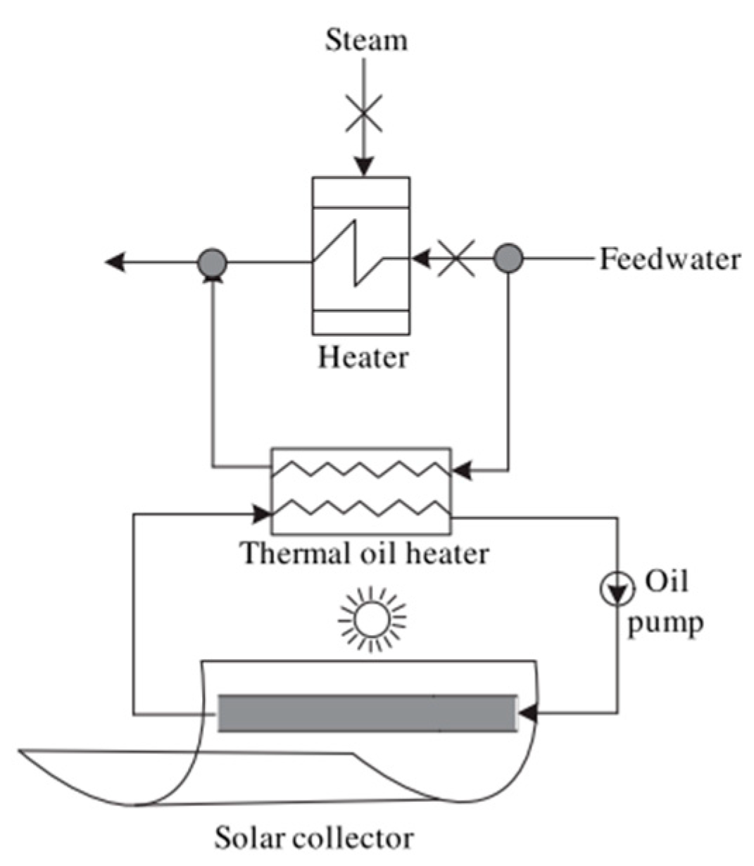
Coal-fired units bring greenhouse effect, environmental pollution, energy shortage and other problems. The above problems can be solved by increasing the proportion of renewable energy. But solar energy, wind energy and other renewable energy are still unstable, discontinuous and high-cost problems. When combined, the two produce stable, low-carbon electricity and heat[27]. As early as 1975, ZOSCHAK et al.[28] proposed a system of complementary integration of solar heat and coal. Based on an 800 MW coal-fired power station, the thermal performance of the replacement regenerator, superheater and reheater by solar energy is preliminarily analyzed. Hu[29] proposed a concept which added solar energy to the traditional coal-fired power station. The system not only improves the efficiency of conventional coal-fired power stations while reducing greenhouse gas emissions, but also provides a good way to generate electricity from solar thermal power. Yang et al.[30] integrated low- and medium-temperature solar power with conventional coal-fired power plants. A 200 MW coal-fired power plant is selected as a case study. The results show that the application of solar energy to power generation has great potential and effect. The schematic diagram of this plant is shown in Figure 5.
In order to reduce greenhouse gas emissions from fossil fuel power plants, Popov et al.[31] proposed a scheme of solar preheating water supply. The thermos-flow software was used to model this system. The results show that the solar power generation share can reach up to 23% of the power plant capacity in this case, having efficiency higher than 39% for the best solar hour of the year. For efficient use of solar energy, Zhang et al.[32] combined tower solar energy with supercritical coal-fired boiler. Two schemes of heating superheated steam and supercooled water by solar energy are put forward. Then thermodynamics and heat transfer models are established. A 660 MW supercritical generator set is taken as an example. The results show that the standard coal consumption of power generation can be reduced by more than 17g/ (kW·h). Zhu et al.[33] used a conventional and an advanced exergetic analysis of a 1,000 MWe solar tower aided coal-fired power generation system, while analyzed exergy distribution of the system, exergy efficiency of each component and exergy destruction construction. Results indicate that the exergy efficiency of boiler and solar tower field systems are 53.5% and 26.0%, respectively.

2.1.3. Biomass-based co-generation system

Co-generation system is not only an energy saving and environmental friendly for energy conversion and utilization[34], but also can effectively reduce carbon emissions. The carbon emissions are still high[35]. In order to effectively promote CO2 emission reduction and accelerate the realization of ‘carbon peak’ and ‘carbon neutrality’, biomass can be used. Biomass is a carbon-neutral renewable energy with rich content and great potential. At present, biomass utilization can be divided into direct burning power generation, biomass and coal co-fired power generation.
  • DIRECT BURNING POWER GENERATION
Direct burning of biomass is the most common form of utilization. The principle of it is similar to that of traditional coal-fired power generation, except that coal is changed into biomass for combustion. Because of its low cost and easy conversion of biomass energy into heat and power. Moreover, it is cheaper to integrate combustion with other technologies of energy generation[36]. In 1988, the first direct burning power plant was built using straw as fuel in the world, which relies on the technology developed by Danish BWE company, and unit capacity is 5 MW[37]. At present, biomass utilization in Denmark is still produced by straw power plants, as many as 130 have been built. ELYAN of the UK introduced BWE's biomass direct combustion power generation technology to build a 38 MW straw power plant in the east, which consumes enough 400,000 bundles of straw every year to meet the daily electricity demand of 80,000 local households. In 2008, the UK also built a 350 MW biomass power plant on the disused harbour at Talport port in south Wales to meet its CO2 reduction targets. According to the environmental factors of local sugarcane production, Cuba also built a biomass power plant using bagasse as raw material with the help of the United Nations organization. The development of biomass direct combustion power generation is late but very fast in China. In 2006, the first large-scale biomass direct combustion power generation demonstration project was put into operation, a 25 MW biomass power plant, which can generate electricity equivalent to 100,000 tons of standard coal every year. For sulfur, carbon and other pollution emissions are significantly reduced. Under the target of carbon peaking and carbon neutrality, the number and capacity of biomass direct-combustion generating units are increasing year by year.
  • BIOMASS AND COAL CO-FIRED POWER GENERATION
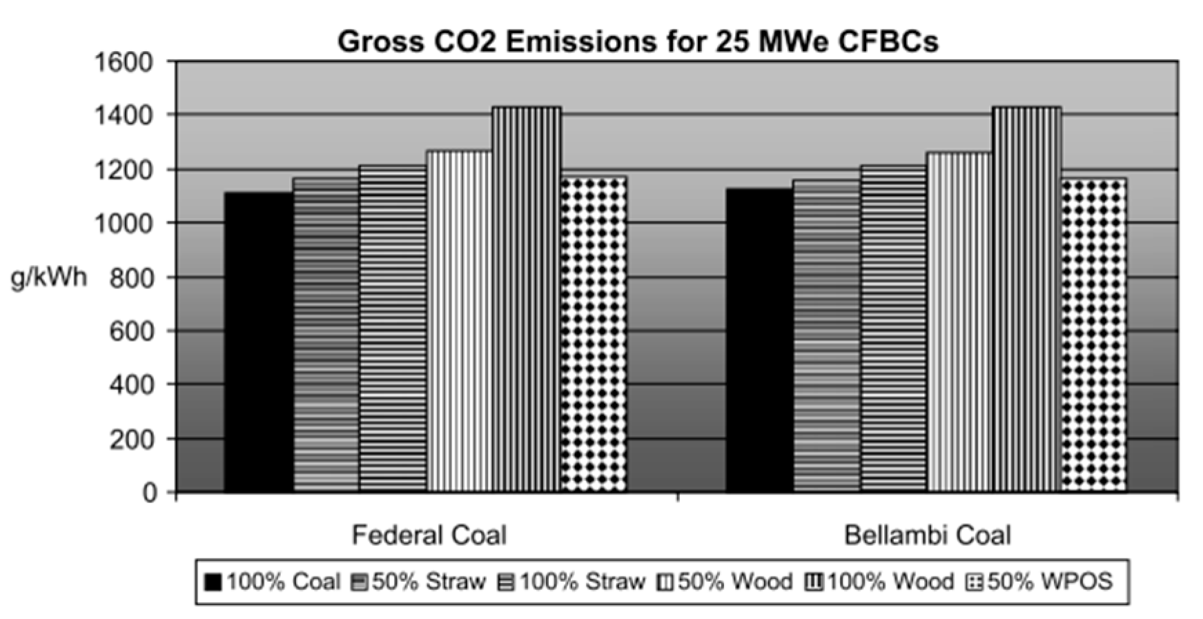
In the process of direct combustion, biomass is prone to ash slagging and corrosion. To solve these problems, biomass can be mixed with coal burning. At this time, due to the addition of coal, the alkali metal and chlorine content concentrations in biomass fuel become lower, and the boiler availability can reach the level of coal-fired boilers. There are many scholars in this field of research. Wright et al.[38] analyzed twenty-five processes concerned with the use of biomass in circulating fluidized bed combustion systems based on actual power plants. It has been shown that circulating fluidized bed combustion power plants of different sizes could operate effectively and efficiently with a range of biomass types and loads in co-firing applications with lower net CO2 emissions. The following figure shows the impact of different coal on total carbon dioxide emissions.
Figure 6. The effect of different coals on gross CO2 emissions.
Preprints 71908 g006
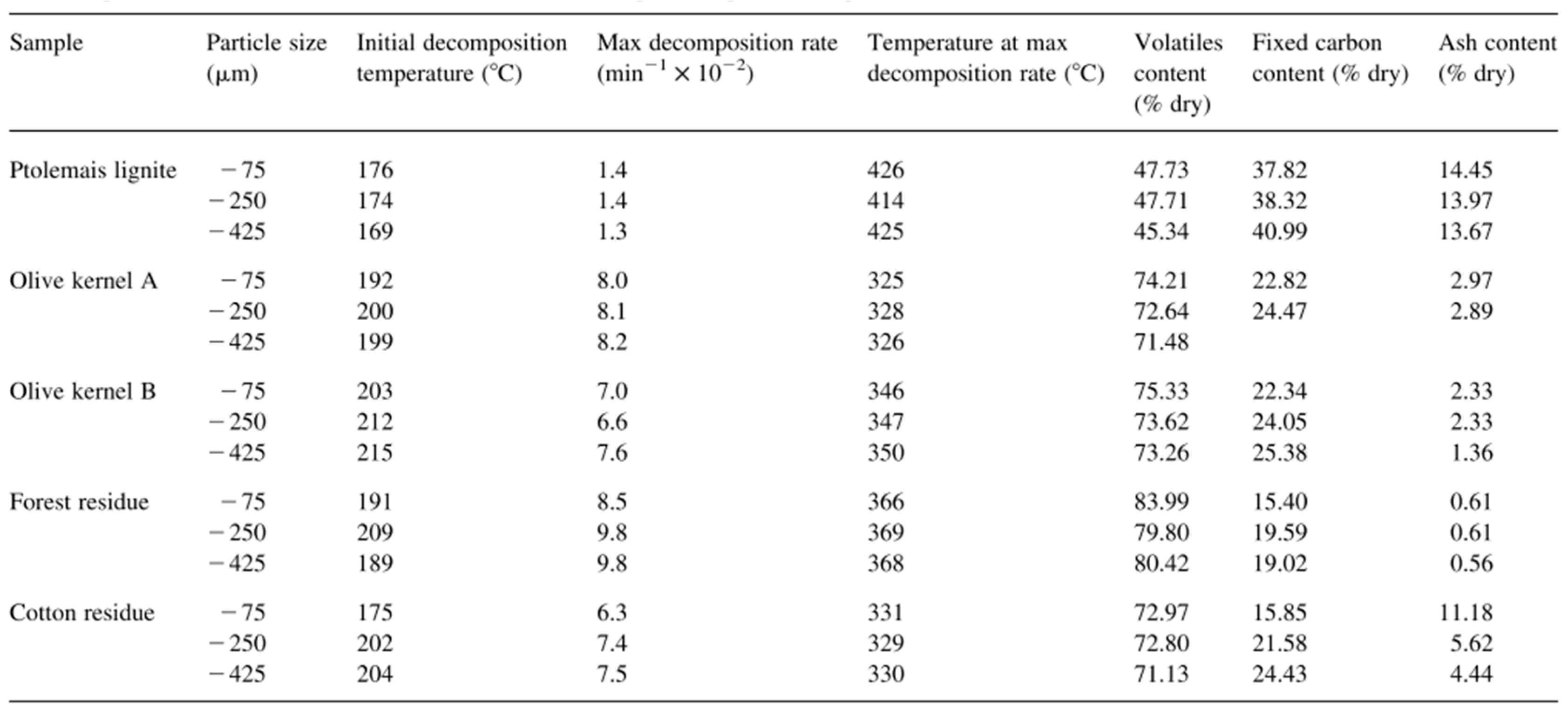
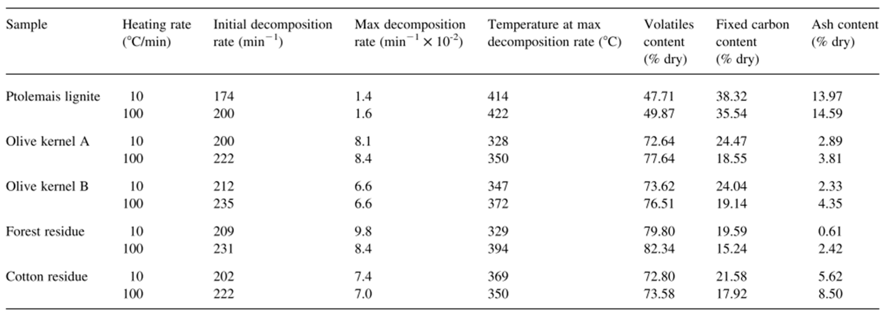
Kastanaki et al.[39] added biomass to the fuel at the ratio of 5%, 10% and 20%wt. for mixed combustion, and then conducted the study by thermogravimetric method. All the tests were conducted in nitrogen atmosphere. The results show that under the same experimental conditions, there is no obvious interaction between the solid phase of coal-biomass mixture. Vamvuka et al.[40] studied the kinetic parameters and volatilization characteristics of olive kernel, wood and cotton residue in the temperature range of 25-850oC when used alone or in combination with coal. The results show that biomass can support the combustion of lean coal, because the volatile compounds are released faster and in greater quantities. The figures show the effect of particle size and heating rate on the devolatilization characteristics of pure samples (heating rate: 10oC/min).
Table 1. Effect of particle size on the devolatilization characteristics of pure samples (heating rate: 10oC/min).
Preprints 71908 i001
Table 2. Effect of heating rate on the devolatilization characteristics of pure samples (Particle size: -250 μm).
Preprints 71908 i002

2.2. CHP based on organic Rankine cycle

Clean and efficient utilization of low- and medium-grade heat energy is one of the trends of future development. The working medium of ORC allows them to operate in the temperature range of 65oC to 200oC[41]. ORC has the advantages of simple structure, automatic operation, low maintenance, independent and flexibility[42]. However, due to the limitation of the working medium’s temperature, the power generation efficiency of ORC system is much lower than that of the power generation system using high temperature heat source. Therefore, it is necessary to integrate with multiple energy systems and develop co-generation systems based on ORC[43].

2.2.1. System integration of renewable energy driven CHP
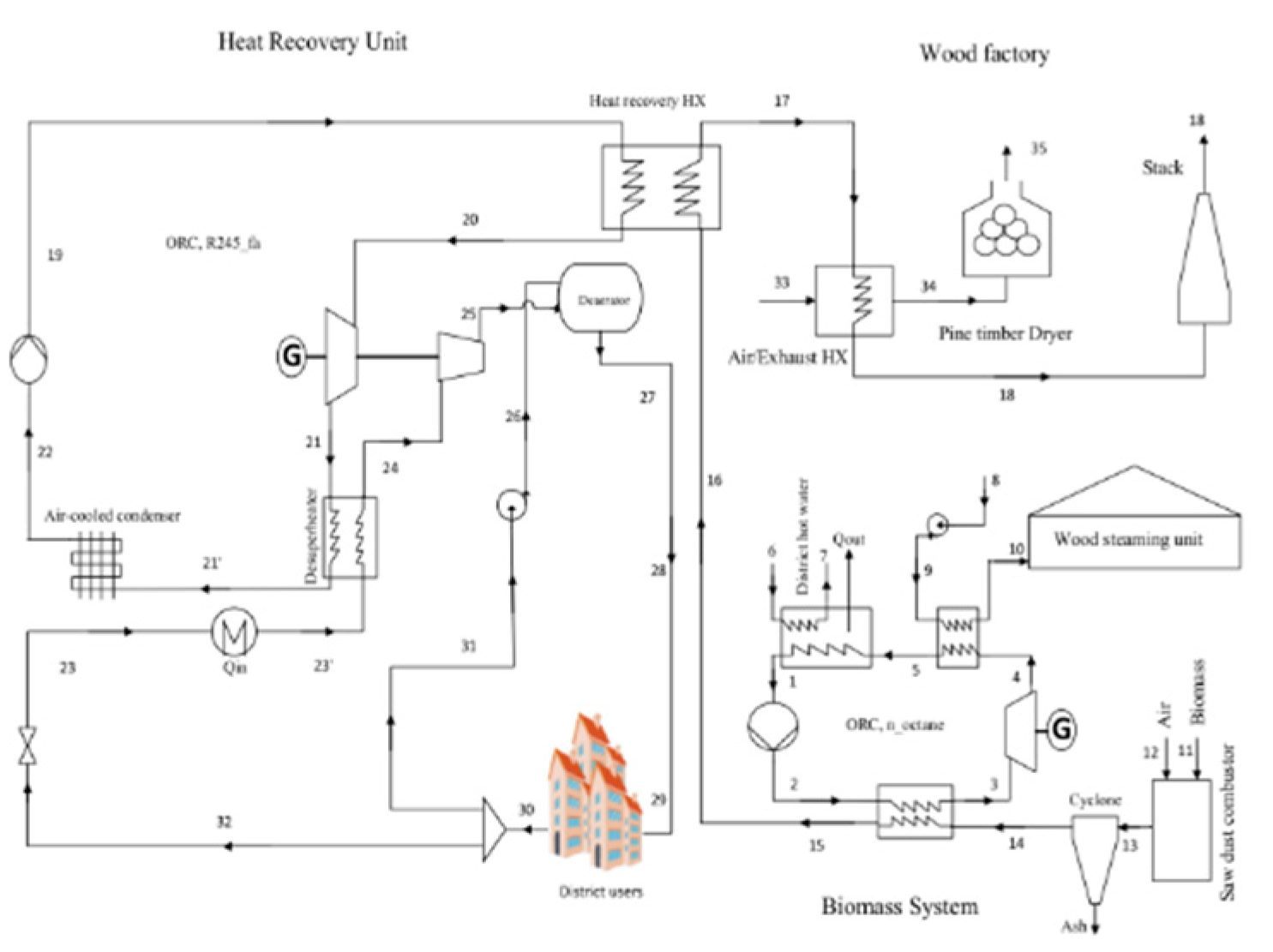
Soltani et al.[44] proposed a multi-generation energy system including ORC with one fuel intake (sawdust biomass fuel) and five useful outputs and carried out energy and exergy analyses to assess its performance. It was found that using a deaerator could increase the hot water mass flow by 10% under the same conditions, rather than using a simple heat exchanger to meet the needs of district heating. A co-generation system has an energy efficiency of about 60% and an exergy efficiency of 25%, while a biomass system that only generates electricity has an energy efficiency of 11% and an exergy efficiency of 13%. The following figures show the schematic of multi-generation system and exergy balance equations for system components.
Figure 7. The schematic of multi-generation.
Preprints 71908 g007
Karellas et al.[45] conducted thermodynamic modeling and economic analysis of a co-generation system operated jointly by organic Rankine cycle and steam compression cycle. In summer mode, some of the power generated by the ORC turbine is consumed by the steam compressor, while the remaining power is converted to electricity. The heat generated by the condenser is used to meet the hot water requirements. In winter operation mode, the steam turbine is disconnected because refrigeration is not required. Boyaghchi et al.[46] analyzed and simulated an advanced solar powered cold, heat and electricity co-generation system based on the double organic Rankine cycle and selected four working media, namely R134a-R245fa, R1234yf-R245fa, R1234ze-R236fa and R423A-R236fa. The results showed that R1234yf-R245fa had a positive impact of 16.71% and 24.34% on energy efficiency and exergic efficiency in November, respectively. Montazerinejad et al.[47] proposed a new type of solar combined cooling, heat and electricity generation system. Exergic analysis, exergic economic analysis and exergic environmental analysis are used to evaluate the performance of the system. Exergic loss and cost of exergic loss of storage tank are the highest through the analysis of code written in EES software. Of the 7.3 kW exergic damage, 5.26 kW was unavoidable.
The exergic performance of a new multigeneration system with parabolic trough solar collector and organic Rankine cycle was evaluated by Al-Sulaiman[48]. In this system, the necessary cooling energy is provided by a single-effect absorption chiller and the necessary heating energy is provided by a heat exchanger. The exergic efficiency was studied by the changes of ORC evaporator pinch temperature, ORC pump inlet temperature and turbine inlet pressure. Exergic loss was mainly caused by solar collector and ORC evaporator. Therefore, the selection and design of these two components can increase the exergic efficiency of the system.

2.2.2. Optimization of CHP based on ORC

An issue that needs to be addressed in order to further improve the efficiency of ORC-CHP systems combined with renewable energy sources is the instability of heat sources. For example, solar radiation fluctuates with time and season, and the calorific value of biomass varies greatly in biomass species and water content. Therefore, it is necessary to study the working medium, operation strategy and optimization method used in the system.
Freeman et al.[49] evaluated the annual performance of the system in terms of total generation and cost per unit of generation. The hot water cylinder and bypass valve are designed by means of electric heat determination. Uday et al.[50] determined the system performance of three integration strategies. The first strategy is hot storage integration (TSI), continuous heating in a certain period of time. The second strategy is direct solar integration (DSI), directly drive co-generation systems. The third strategy is direct solar and heat storage integration (DST-SI), namely hot water from co-generation is returned to heat the heat storage tank. The DSTSI policy provides the best performance. Javan et al.[51] studied the comprehensive techno-economic model of the co-generation system, taking into account two main objective functions: maximizing the exergic efficiency of the system and minimizing the total cost rate of the system. Kang et al.[52] proposed a new coupling system that combines a combined heating and power system with a heat pump system. The energy efficiency and motion efficiency of the system are 142.2% and 22.6% respectively. The key parameters such as generator capacity and heat pump outlet temperature were optimized by genetic algorithm to maximize the comprehensive performance. Ozlu et al.[53] conducted a thermodynamic analysis on a co-generation system based on renewable energy sources. A solar collector area is 24 m2. The maximum energy efficiency and exergy efficiency is 36% and 44%, respectively. The total work output for electricity is 116 kW, and the CO2 reduction is 476 tons per year. The optimum number of suites, as an application for a building complex, which can be sustained with the proposed system is determined as 106 suites. Ahmadi et al.[54] reported a comprehensive thermodynamic modelling of a co-generation system for cooling, heating and electricity generation. Energy and exergy analyses, environmental impact assessments and related parametric studies are carried out, and parameters that measure environmental impact and sustainability are evaluated. Mago et al.[55] studied the energetic, economical, and environmental performance of a combined CHP-ORC system and compared its performance to a standalone CHP system and a reference building for different climate zones. Wang et al.[56] presented a multi-objective optimization of a combined cooling, heating and power system driven by solar energy. The final solutions in the multi-objective optimization of the system operating in three modes, namely power mode, combined heat and power mode, and combined cooling and power mode. For the first mode, the optimum average useful output and total heat transfer area were 6.40 kW and 46.16 m2. For the second mode, the optimum average useful output and total heat transfer area were 5.84 kW and 58.74 m2. For the last mode, the optimum average useful output and total heat transfer area were 8.89 kW and 38.78 m2.
Table 3. The main contents of the literatures in this part are summarized in the table below.
Author(s) Brief Title Highlights Ref.
Freeman et al.
(2015)
An assessment of solar-powered ORC systems for CHP An average electrical power of 89W plus an 86% hot water coverage are demonstrated. A total system cost as low as £2700 and a levelised cost electricity of 44 p/kW h are reported. [50]
Uday et al.
(2016)
Performance analysis of solar cogeneration system System utilizes solar thermal energy for the operations without auxiliary heaters. Three different system integrations are experimentally investigated in UAE. Economical benefits of solar cogeneration system are also reported. [51]
Javan et al.
(2016)
Fluid selection optimization of a (CCHP) system Feasibility study of employing CCHP from waste heat of ICE for residential buildings. Working fluid selection for low grade waste heat recovery. Multi-objective optimization of a CCHP system. [52]
Kang et al.
(2017)
A CHP-HP Coupling System and Optimization Analysis The energy efficiency and motion efficiency of the system are 142.2% and 22.6% respectively. [53]
Ozlu et al.
(2016)
Performance assessment of a new multigeneration system The maximum energy efficiency and exergy efficiency is 36% and 44%, respectively. The total work output for electricity is 116 kW, and the CO2 reduction is 476 tons per year. [54]
Ahmadi et al.
(2012)
Exergo-environmental analysis of a ORC for trigeneration The thermodynamic modelling and exergoenvironmental analysis of a trigeneration system. The exergy results show that combustion chamber and heat exchanger are the two main sources of irreversibility. [55]
Mago et al.
(2010)
Analysis and optimization of CHP-ORC systems For the 24h a day operation, the average cost, PEC, and CDE reductions are 25.9%, 26.1%, and 26.5%, respectively. For the 12h a day operation, they are 19%, 19%, and 20%, respectively. [56]
Wang et al.
(2015)
Multi-objective optimization of a CCHP driven by solar energy Multi-objective optimization of a combined cooling, heating and power system driven by solar energy. [57]
The organic Rankine cycle system can achieve high cycle efficiency in the medium and low temperature heat source, and the total installed capacity can be reduced to kilowatt level, which is a promising medium and low temperature and small capacity power generation technology. With the gradual development of co-generation system to miniaturization and civilianization, the micro-cogeneration technology based on organic Rankine cycle has a broad development prospect.

2.3. Stirling cycle

The Stirling engine is an external combustion engine which outputs power through a cycle of cooling, compression, heat absorption and expansion of the working medium (hydrogen or helium) in the cylinder[57]. There are three configurations of the Stirling engine, including Alpha, Beta, and Gamma[58]. Co-generation systems using Stirling engines as prime movers have numerous benefits such as the ability to burn multiple fuels and low emissions of pollutant[59]. Based on this, many scholars have conducted research on it.

2.3.1. Biomass driven systems

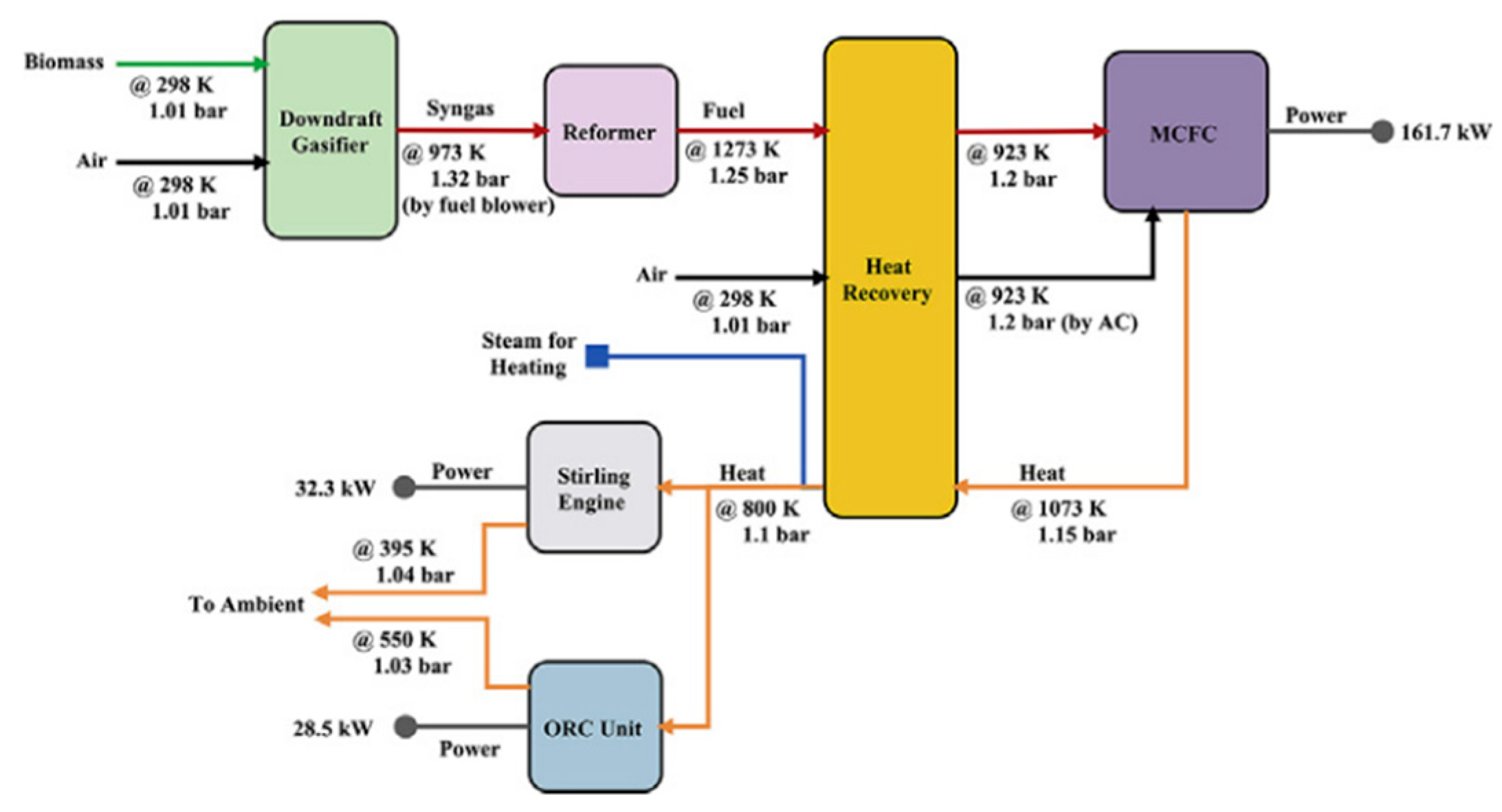
Salehi et al.[60] thermodynamically analyzed a combined CHP system that integrates a biomass gasifier, molten carbonate fuel cell, heat recovery steam generator, Stirling engine, and organic Rankine cycle to determine the potential of this system compared to conventional systems. The results revealed that the maximum value of exergy efficiency is 50.18% with CO2 emissions of 28.9×10⁻²t/ (MW·h). The following figure is the graphical abstract.
Figure 8. The graphical abstract of CHP system.
Preprints 71908 g008
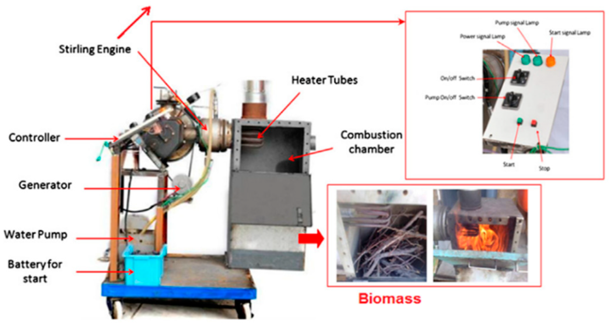
Considering the potential of biomass, Damirchi et al.[61] designed, optimized and built a Gamma Stirling engine using helium as its working medium. The key parameters of Stirling engine are calculated by thermodynamics and heat transfer. At the maximum power, the internal thermal efficiency of the engine was measured to be 16%. And maximum power (25.79 W) was obtained from sawdust and minimum for wood (10.71 W). This graphical abstract of this article is also shown in the following figure.
Figure 9. The graphical abstract of reference[61].
Preprints 71908 g009
Cardozo et al.[62] focused on the experimental evaluation of the integration of a 20 kWth wood pellet burner and a 1 kWe Stirling engine. The relation between temperature of the hot side end and thermal power absorbed by the Stirling engine is nearly linear between 500oCand 660oC. Higher pressure inside the Stirling engine has a positive effect on the thermal power output. The overall efficiency of the Stirling engine system reached 72%. Chen et al.[63] introduced a combined cooling, heat and power generation system including gasification system, Stirling engine system and absorption chiller system. The system has the ability to reduce tar condensation and contamination. Compared with the conventional reference system, the average total cost of the newly proposed optimized system is reduced by 75.9% and 70.5% respectively. Najafi et al.[64] designed a typical co-generation system using gamma Stirling engine as prime mover, then presented the combustion test results which is a key technology for small and micro scale CHP systems and discussed the combustion parameters for the Gamma type Stirling engine power system. Also, analysis of pollutants showed that by increasing of sawdust mass flow rate from 0 to 0.14g/s, CO emissions increased 164 vol%, also HC and NOx emissions increased 295-24 ppm respectively. Udeh et al.[65] mixed Stirling prime mover and ORC to design a CHP system. The system used the waste heat to generate additional power, while the waste heat recovered from the flue gas is used to dry biomass and produce hot water. The effects of heating and cooling load, prime mover speed and biomass fuel on system performance were studied by sensitivity analysis. The study found that combining Stirling engine and ORC improved power output and thermal efficiency by 66% and 63.4%, respectively, over using the Stirling machine alone. The schematic of the proposed hybrid Stirling engine and ORC bottoming cycle driven CCHP system is shown in the following figure.
Figure 10. The schematic of the hybrid Stirling engine and ORC bottoming cycle driven CCHP system.
Preprints 71908 g010
Arashnia et al.[66] designed and optimized a micro co-generation system based on the Stirling machine. The electric power output of the plant was 100 Watts and used wood flour as fuel. Its performance was studied according to operating conditions, heat flux, temperature and biomass type. The results showed that the system was most efficient when the Stirling engine was rotating at around 500-600 rpm.

2.3.2. Solar and fossil energy as fuel
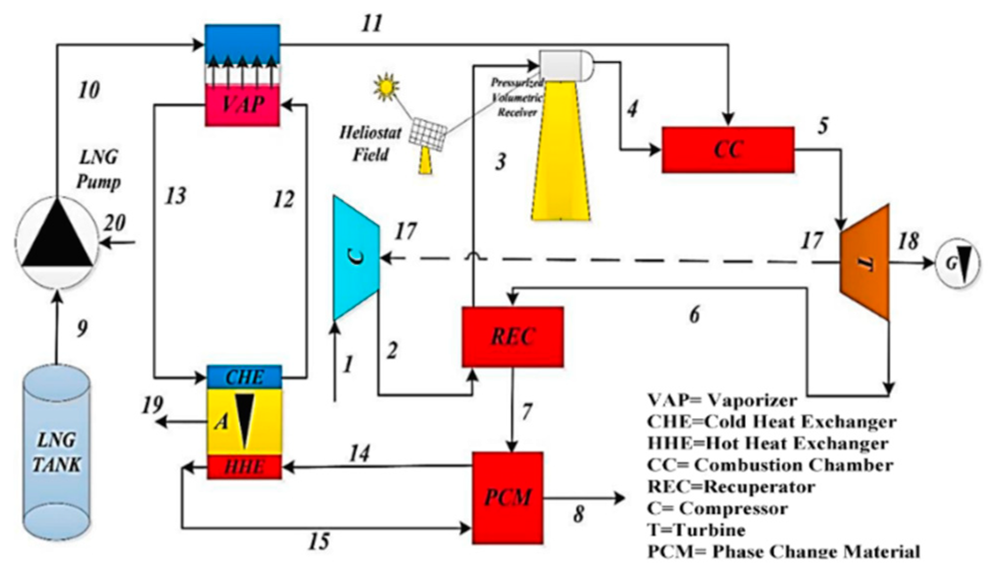
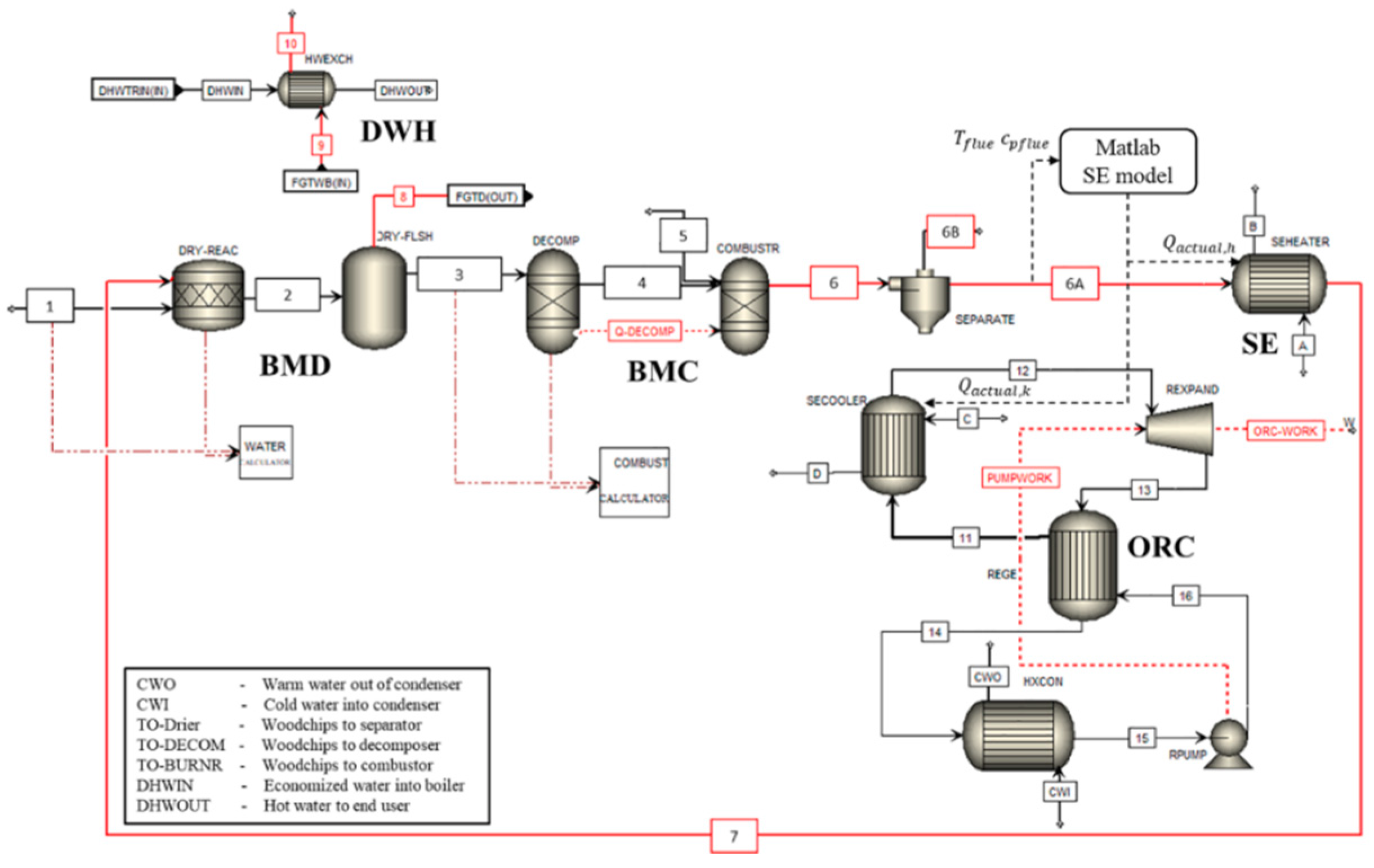
SOLO Company in Germany et al.[67] has studied Stirling heat engine which uses solar energy and biomass as heat source. The heat source is mainly composed of high temperature sodium heat pipe collector, which can use both solar energy and biomass as heat source. Its use makes the heat absorber temperature of Stirling heat engine can be uniformly maintained at about 800oC, effectively reduce the thermal stress at the heat source, prolong the service life. Doerte et al.[68] developed a hybrid heat pipe receiver which had a designed power of 45 kW and a designed operating temperature of 700~850oC. Tests show that the dish system using the receiver has a solar thermoelectric efficiency of 16% alone, gas thermoelectric efficiency of 17% alone, and combined operation thermoelectric efficiency of 15%. The development of the hybrid heat pipe receiver is conducive to improving the adaptability of the dish solar thermal power system and realizing continuous power supply. However, due to the addition of the combustion system, the structure becomes very complicated, the difficulty of processing and manufacturing increases, and the cost increases greatly. Moghadam et al.[69] proposed a co-generation system with a solar dish Stirling engine, a hot water natural gas boiler and a absorption chiller to generate power, heat and cool. Then the 3E analysis evaluated primary energy saving analysis (energy analysis), carbon dioxide emission reduction (environmental analysis) and payback period for return of investment (economic analysis). The results show that this micro-CHP system had good potential in primary energy saving and carbon dioxide emission reduction in all scenarios and acceptable payback period for return of the investment in some scenarios. Babaelahi et al.[70] described a new system that uses solar energy for most of its energy needs and liquefied natural gas fuel as an auxiliary source. The artificial intelligence tool Genetic Programming was used to optimize the system by multiple fitting. The results showed that the thermal efficiency and work efficiency are increased by 6.252% and 8.842% respectively at the optimum point. The schematic view of the proposed power generation system is shown in the following figure.
Figure 11. The schematic view of the proposed power generation system.
Preprints 71908 g011
Stirling engine exhaust temperature is high to recycle easily. However, its cooling water temperature is relatively low, and the heat taken away by the cooling water accounts for a larger share of the total input energy. Stirling engine technology is not mature at present, and the co-production system with Stirling engine as prime mover still needs to be further studied.
The existing literature has discovered through analysis that the combustion process of the external combustion heat engine has the highest irreversible losses in the current system. A change in the power generation unit, such as switching the external combustion engine to an internal combustion engine, may be an effective strategy to eliminate these irreversible losses.

3. CHP based on internal combustion cycles

The internal combustion engine is a heat engine that produces heat energy that is directly turned into power by burning fuel inside the unit. It is distinguished by its compact design, light weight, and high level of effectiveness. Regular representatives include gas turbine and reciprocating engine.

3.1. Gas turbine co-generation system

The gas turbine can effectively utilize the heat below 1500oC. Compared with steam turbine system, the utilization of high temperature is significantly improved. In a gas turbine system, air is passed through a compressor reaching higher temperature and pressure. Then it goes into the combustion chamber and then burns with the fuel. The combustion mixture is then sent to a turbine to generate electricity[71]. Since the temperature of the gas turbine may exceed the melting point of construction materials, cooling measures should be taken[72]. Gas turbines can be divided into large-scale gas turbine and micro gas turbine according to different application scenarios. Large-scale turbines are typically used in power plants, while micro-turbines are typically used in small applications such as construction, industrial and decentralized energy generation.

3.1.1. CHP with large-scale gas turbines or combined cycles
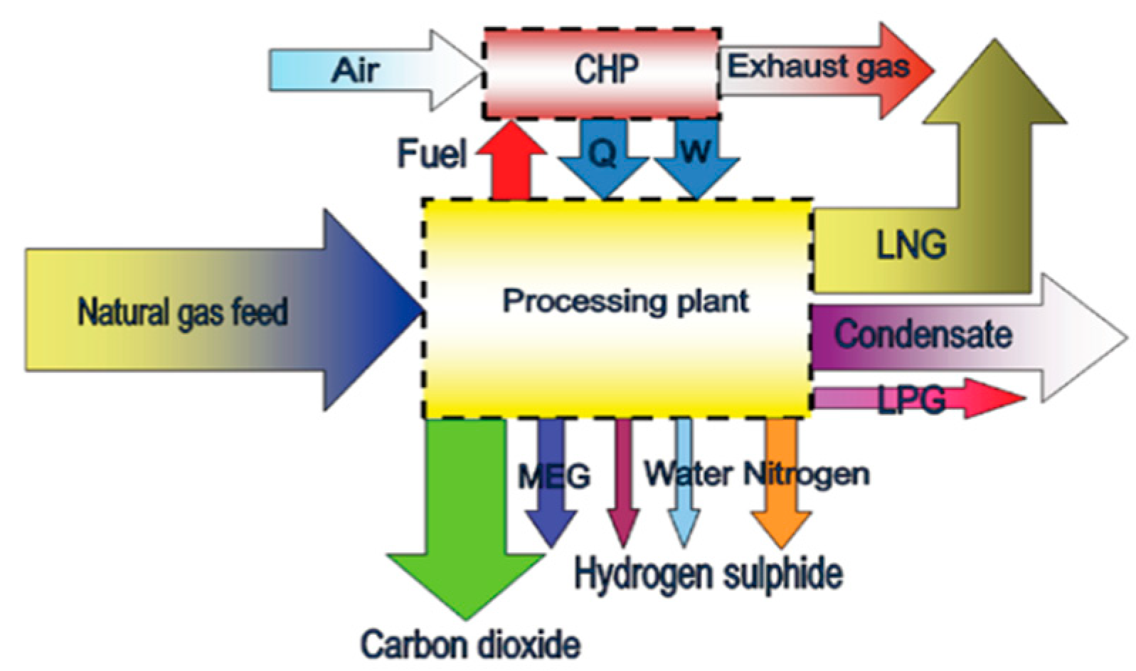
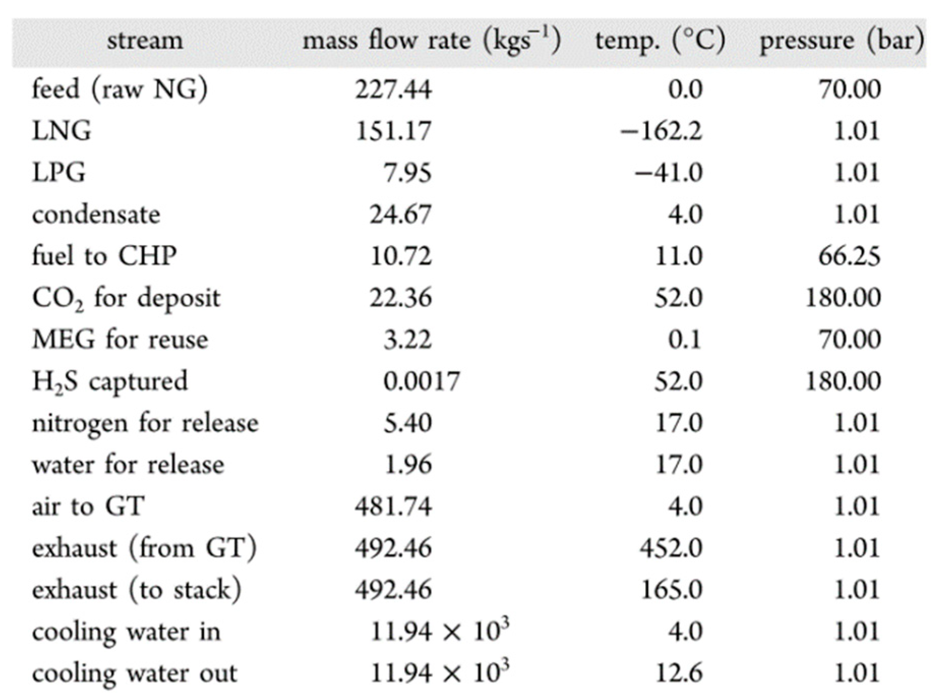
Rian et al.[73] compared the performance of a combined heat and power in three different ambient temperatures. From the results, it was shown that the exergy efficiency increased under cold weather conditions. For example, at 4oC, 20oC, and 36oC, the exergy efficiency was reported as 43.5%, 42.7%, and 41.9%, respectively. The system of analysis and the key data are shown in the following figure and table, respectively.
Figure 12. The schematic diagram of system.
Preprints 71908 g012
Table 4. The key data of new system.
Preprints 71908 i003
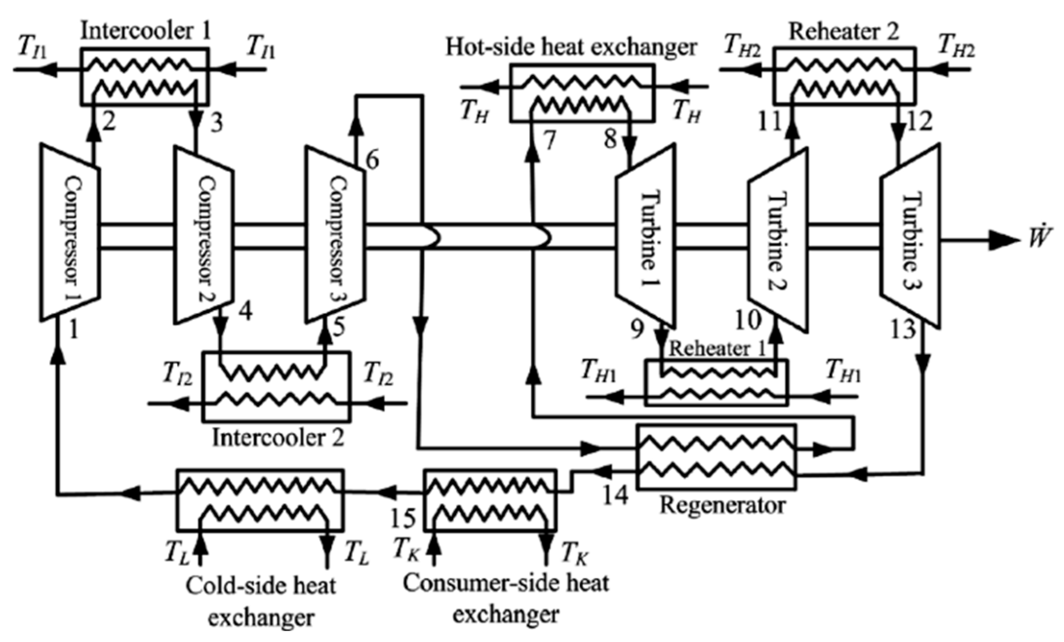
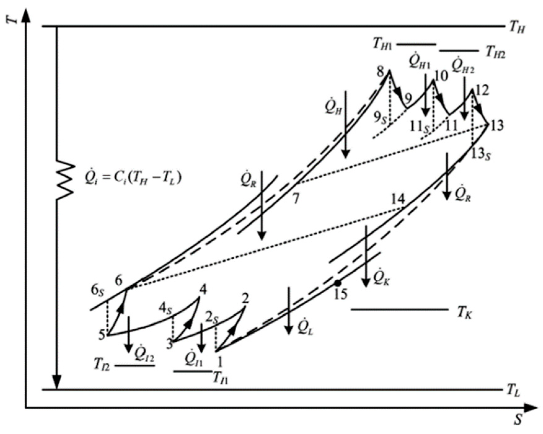
Yoru et al.[74] provided a comprehensive analysis of co-generation systems. The system has three gas turbines with a total capacity of 13 MW, six dryers and two heat exchangers. Based on the data model of 720 h, it is found that the average energy efficiency and operation efficiency of the system are 82.3% and 34.7% respectively. Ahmadi et al.[75] deals with a comprehensive thermodynamic modeling of a combined heat and power (CHP) system in a paper mill. The results show that at the lower exergetic efficiency, in which the weight of exergoenvironmental objective is higher, the sensitivity of the optimal solutions to the fuel cost is much higher than the location of the Pareto Frontier with the lower weight of exergoenvironmental objective. Yang et al.[76] proposed a co-generation system consisting of an irreversible constant temperature heat source, a two-stage intercooling regenerative reheat closed Brayton cycle and a heat recovery device based on the finite time thermodynamics. Two cases of constant pressure ratio and variable pressure ratio are discussed and optimized. The sketch and T-s diagram of a real CHP plant are shown in Figure 13 and Figure 14.
Hou et al.[77] proposed a co-generation system consisting of a supercritical CO2 recompression cycle, two trans-critical CO2 refrigeration cycles, and a steam generator. The comprehensive thermodynamic analysis and economic analysis of the whole system were carried out. Through parameter analysis, the influences of key operating parameters such as air compressor pressure ratio, S-CO2 compressor inlet pressure, S-CO2 circulating pressure ratio on system performance were studied. The result indicates that by using the CCHP system, 4.99 MW of power, 0.58 MW of heat capacity, and 0.63 MW of refrigeration capacity can be recovered from the exhaust gas.

3.1.2. CHP with micro gas turbine

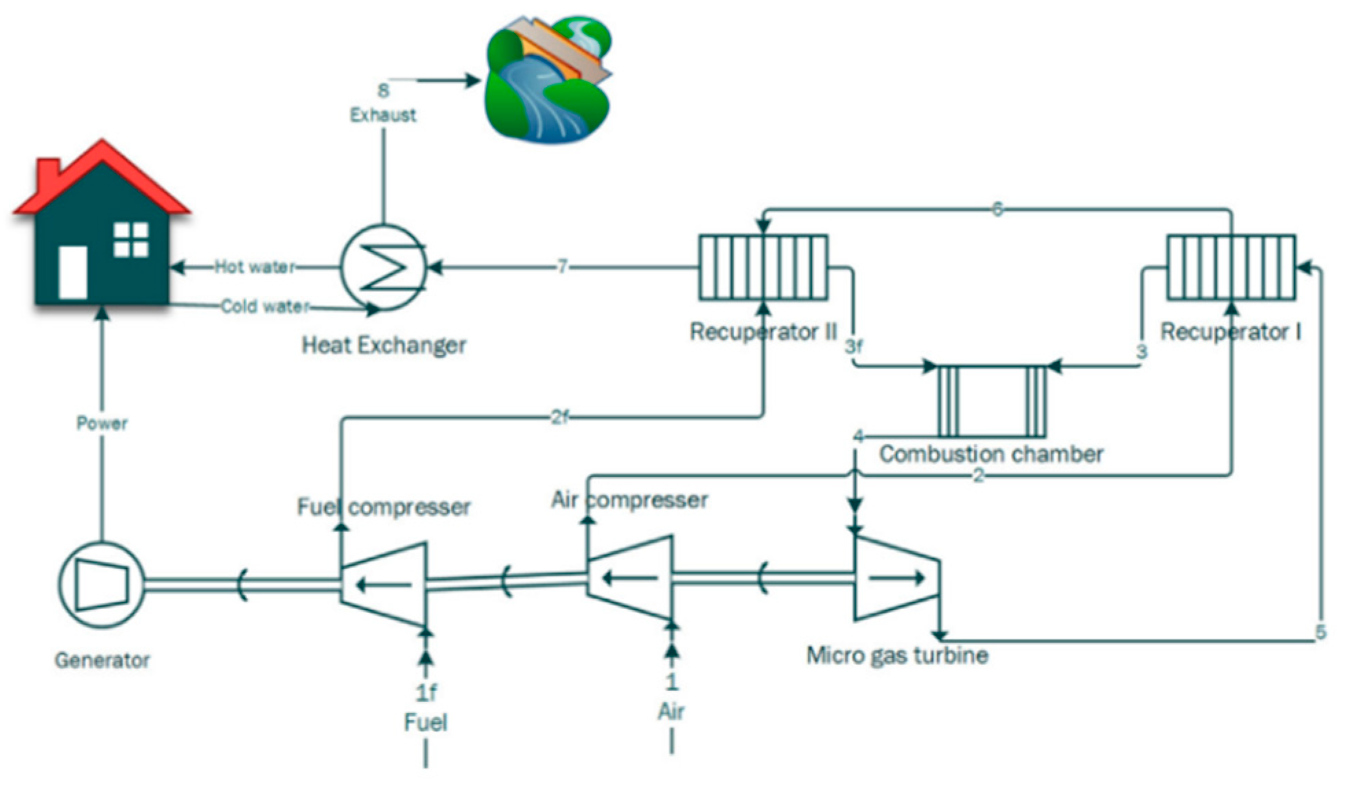
Micro-cogeneration, also termed micro combined heat and power (MCHP), is an emerging technology with the potential to provide energy efficiency and environmental benefits by reducing primary energy consumption and associated greenhouse gas emissions[78]. Figure 15 shows the schematic representation of micro gas turbine CHP.
Balli et al.[79,80] performed thermodynamic analysis of a co-generation system with a microturbine as the prime mover for the first time. The energetic and exergetic efficiencies of this system are 75.99% and 35.8%, respectively. Celador et al.[81] performed the thermoeconomic analysis of the micro-CHP installation for its annual operation which includes the analysis of the entire system, considering the costs and exergy content of both flows and components. The diagram of the micro-CHP plant is shown in the following figure.
Figure 16. The diagram of the micro-CHP plant.
Preprints 71908 g016
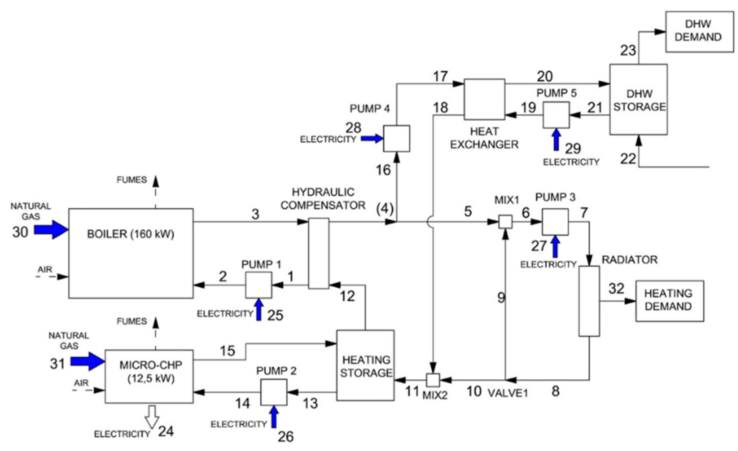
Thu et al.[82] constructed a cogeneration system with a micro gas turbine which the capacity is 65 kW as the prime mover. The second law analysis and the Energy Utilization Factor technique are used to evaluate the performance of the system. The actual chemical composition of the materials used is also considered. The result showed that the exergic loss of combustion chamber accounted for 70% of the total exergic loss. The first law efficiency of the system is 15.7% at 25% load and 28.95% at full load. Under full load condition, the second law efficiency of the whole system is about 30.4%. Pirkandi et al.[83] developed a MATLAB code to simulate and optimize the thermoeconomic performance of a gas turbine based CHP cycle. Three design parameters of this cycle considered in this research are compressor pressure ratio, turbine inlet temperature, and air mass flow rate. The schematic diagram of the cycle power plant is shown in the following figure.
Figure 17. The schematic diagram of the cycle power plant.
Preprints 71908 g017
Lei et al.[84] established and analyzed a partial load model of the combined cooling and thermal power generation system. The results show that the micro-gas turbine and bottom absorption chiller are coupled by flue gas energy. Four different supplementary strategies (load adjustment method, mass flow first method, temperature first method and maximum coefficient of performance method) had been proposed and analyzed when flue gas heat was insufficient. The results show that the load regulation method has the largest fuel consumption. When the flue gas heat is insufficient, it is recommended to use the temperature priority method supplement strategy.
When the CCHP system is applied to building users, it is still dominated by small gas turbine CCHP system. This is because the cooling temperature required by the building user is usually close to the ambient temperature, and long-distance transmission is quite difficult. Therefore, large-scale gas turbine co-generation system is rarely used. Generally, units with capacity below 20 MW are widely used in the field of co-generation system.

3.2. CHP based on reciprocating engine

Reciprocating engines generally use gasoline, diesel or gas fuel combustion to generate pressure. It is usually one or more pistons. Each piston is in the cylinder. The mixture of fuel and air is injected into it, and then ignited (the diesel engine is compression ignited) to expand the gas and push the piston to move. Many scholars have analyzed the efficiency of the co-generation system with reciprocating engine as the prime mover.
Celador et al.[85] studied the feasibility of an ICE-based CHP with three different hot water tanks in buildings. It was shown that the exergy efficiency of all three models was nearly the same, near to 26%. Ehyaei et al.[86] constructed a CHP system with an internal combustion engine to provide electricity, hot water, heating and cooling for residential buildings. Exergic analysis is used to investigate the technical, economic and environment of the system. The average annual power cost of the system is 0.05 US$/(kW·h) and the annual entropy production of the system is 29903 GJ/year. Li et al.[87] analyzed the energy balance and efficiency of an internal combustion engine unit fueled by biogas. Results showed that the engine set can generate electricity of 70.0 kW under a biogas yield of 34.84 m3/h in the standard state with the energy efficiency of 28.45% and the exergy efficiency correspond to 27.36%. Rovas et al.[88] presents an exergy analysis of combined heat and power production via gasification of various Mediterranean agro-food processing biomass fuels. The results show that exergy losses were found to be higher in the internal combustion engine, followed by those in gasifier and producer gas conditioning. Darzi et al.[89] studied the detailed energy and exergic distribution of a typhoon-cooled two-stroke engine used in a co-generation system. The engines are fueled by natural gas, methane and propane. It was found that combustion loss and heat transfer loss contributed the most to exergic loss, accounting for about 15% and 9%, respectively. The second law maximum efficiency is about 60.5%, and the first law maximum efficiency is about 29%. Yildirim et al.[90] dealt with exergoeconomic analysis of a CHP system which has a total installed electricity and steam generation capacities of 11.52 MW and 9.0 tons/h at 140oC, respectively. SPECO approach is used in this analysis which is based on specific exergies, and costs per exergy unit, exergetic efficiencies, and the auxiliary costing equations for components of thermal systems. The capital investment cost, the operating and maintenance costs and the total cost of this system is 649 $/h, 149.6$/h and 810.2 $/h, respectively. Goyal et al.[91] describes the performance of a CCHP system based on a single cylinder diesel engine. The decrease in specific fuel consumption was 53.24%, 51.29% and 6.89% in case of CHP, CCHP and CCP mode respectively compared to that in single generation at full load. Aliehyaei et al.[92] carried out exergic, economic and environmental analysis of a multi-generation system with internal combustion engine as the prime mover. Then the entropy production and second law efficiency were calculated. The objective functions of the initial, operation, maintenance and fuel costs of internal combustion engine flue gas and the external costs of environmental pollutants such as CO2, CO and NOx are given. The results showed that the entropy production in co-generation mode is 30% lower than that in simple internal combustion engine mode. Taie et al.[93] provide detailed thermodynamic first and second law performance measurements of the internal combustion engine and generator subsystems of CHP system. At a first law, the maximum electrical efficiency and the maximum utilization factor is 23.9% and 74.5%, respectively. The electrical efficiency used second law analysis is 23.1 0.4%.
Table 5. Summary of the studies about exergy in reciprocating engine-based CHPs.
Author(s) Brief Title Highlights Ref.
Celador et al. (2011) Stratified hot water storage tanks
in CHP
The economic feasibility of using hot water storage tank in residential cogeneration power plant is studied by using TRNSYS software. 83
Ehyaei et al.(2012) ICE in residential buildings Technical, economic, environmental feasibility and exergy evaluation of residential building ICE. 84
Yildirim et al.(2012) Exergoeconomic analysis for a CHP system exergoeconomic analysis of a CHP system, the capital investment cost, the operating and maintenance costs and the total cost of this system is 649$/h, 149.6$/h and 810.2$/h, respectively 88
Li et al. (2014) ICE using biogas Electricity generation of biogas, Water-cooled engine, Heat dissipation, Efficiency of energy usage, energy efficiency of 28.45%, exergy efficiency corresponds to 27.36%. 85
Rovas et al. (2015) Exergy evaluation of a smart-CHP Exergy analysis of thermal power plants powered by ICE and fueled by Mediterranean agricultural food processing biomass; Exergy efficiency is 26% - 33%. 86
Goyal et al. (2015)
Performance of IC engine CCHP
Performance and emission analysis and comparison of single cylinder diesel engine cogeneration, cogeneration and cogeneration. The single generation exergy efficiency is 29.6%. 89
Aliehyaei et al. (2015) Analysis of simple ICE and CHP
ICE
Compared with ICE CHP, the entropy generation of simple ICE in economic and environmental analysis CHP mode is reduced by 30%. 90
Taie et al. (2018) Thermodynamic of an ICE micro-CHP The thermodynamic study of a micro cogeneration system driven by a 1 kW Honda Ecowell engine shows that its electrical efficiency is 23%. 91
Darzi et al. (2019) Thermodynamic investigation of a micro-CHP Study on the influence of gas fuel on two-stroke direct injection engine in small cogeneration system. 87
The inlet temperature of internal combustion engine (ICE) can reach 2000oC. Its efficiency of electricity is slightly more than gas and steam turbines. However, due to the low exhaust temperature of ICE, the heat utilization of the multi-generation system driven by ICE is not as good as that of gas turbine system and steam turbine system, resulting in more work output and less cold and heat output. ICE have a wide power range, from a few hundred watts to a few thousand kilowatts. However, large ICE is at a disadvantage when competing with other heat engines due to large size, high vibration and noise, and are rarely used. At present, small and medium-sized internal combustion units are widely used.

3.3. Efficient use of high-temperature exhaust gas of engine

Waste heat from heat engine exhaust has a high energy grade in conventional co-generation systems, for example, the flue gas temperature of internal combustion engines is typically 400-600oC. Absorption refrigeration and heat pump cycles are effective ways to utilize waste heat, but their driving temperatures are generally not higher than 200oC[94],and there are large irreversible losses when they are simply used downstream of the heat engine cycle to recover flue gas waste heat, which can result in inadequate energy ladder utilization in co-generation systems. With the rapid development and widespread application of co-generation systems, resolving the temperature disconnect of power waste heat utilization has never been more important.
The power/refrigeration coupling cycle system solves the above problem in an efficient and feasible manner. The system simultaneously converts industrial or power waste heat into electrical energy and cold energy or low-temperature cold energy, which can significantly improve energy conversion efficiency and reduce energy consumption while meeting demand of users for electricity and cooling load.
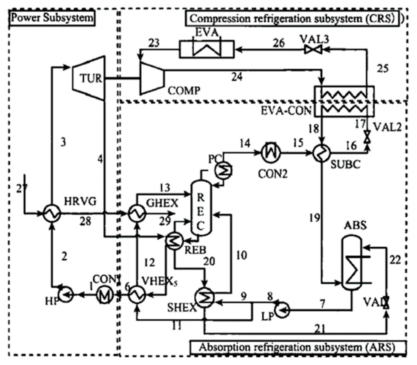
Zhang and Liu et al.[95,96] proposed several power/refrigeration coupling cycles based on ammonia work to utilize gas turbine exhaust heat, primarily in two basic forms, parallel and series, and developed extended forms of systems based on them, such as hybrid and adjustable concentration. The hybrid and adjustable concentration system performance is high, but the system complexity is high, making accurate regulation control difficult. When the heat source flue gas temperature, cooling water temperature, and refrigeration temperature are 465oC, 20oC, and -18oC, respectively, the power-to-chill ratios of parallel and series cycles are 5.68 and 6.48, the energy efficiency is 25.9% and 23.7%, and the exergy efficiency is 58.8% and 54.7%.[97]。Chen Yi et al.[98] proposes a composite refrigeration system that uses a medium-temperature sensible heat source to produce lower temperature cooling capacity, based on the principle of energy utilization and the power/refrigeration coupling cycle method. The system is made up of three sub-cycles: a power sub-cycle, an absorption refrigeration sub-cycle, and a compression refrigeration sub-cycle. The system cooling performance coefficient is 0.277 after simulation, which is approximately 50% higher than that of a conventional waste heat two-stage absorption refrigeration system. Figure 18 is the schematic diagram of the new absorption-compression refrigeration system.
Sun et al.[99] investigated the power/refrigeration cycle coupling mechanisms of medium and low temperature waste heat resources, as well as the mixed mass power-cooling co-generation system and the composite refrigeration system. The results show that when the heat source flue gas temperature, cooling water temperature, and refrigeration evaporation temperature are 350oC, 30oC, and -15oC, respectively, the equivalent energy efficiency of closed and open power-cooling co-generation systems is 18.1% and 19.2%, and the energy saving rate is higher when compared to the split production system. For both, energy savings can reach greater than 20%.
Many additional studies on the power/refrigeration cycle coupled systems have been conducted, and the findings of these studies provide an effective new approach to address the temperature fault of power waste heat utilization and to use medium temperature waste heat to provide low temperature cooling capacity.

4. CHP based on non- thermodynamic cycles

The second type of CHP technologies, which are mostly PVT and fuel cell technologies, is not based on thermodynamic cycles.

4.1. PVT

Solar energy is popular as an accessible and clean source of energy. The conversion of solar energy into electricity and heat has been widely used in the past decade and will be more widely used in the future[100]. PVT systems are able to convert solar energy into electricity and heat at the same time, making it more efficient than current photovoltaic systems[101]. The PVT system consists of two parts: a solar cell, which converts solar energy into electricity, and a solar heat collector, mounted on the back of the PV panel, which collects heat energy. Water or air is often used as a coolant for solar panels[102,103]. As a result, this configuration improves system efficiency. The system efficiency can be increased by more than 80% by using waste heat[104].

4.1.1. Simulation study

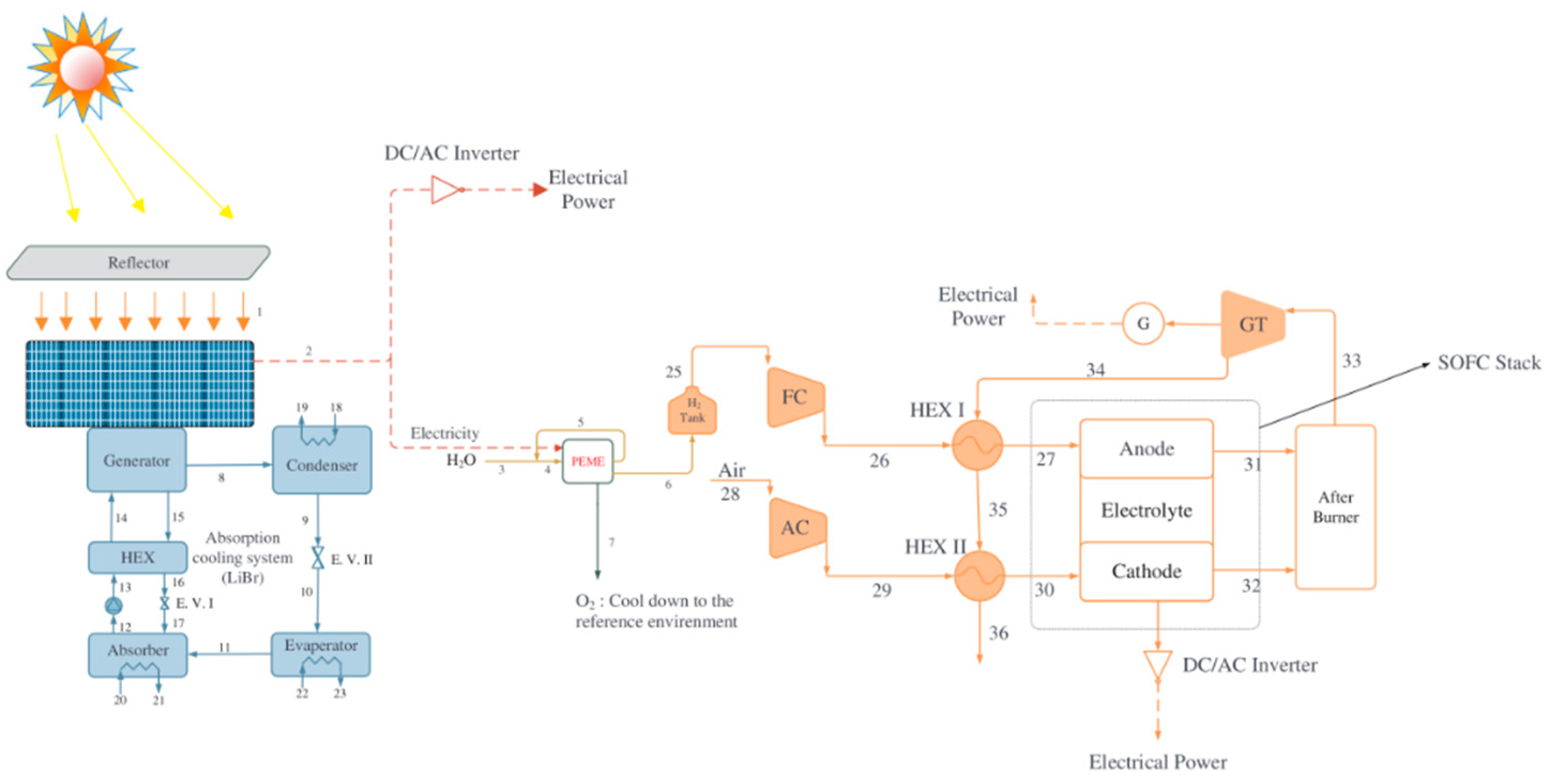
Vorobiev et al.[105] analyzed a solar energy conversion hybrid system with a high temperature. The system contains a radiation concentrator, a photovoltaic solar cell and a thermal generator. Optical and thermal losses were considered, including convection and radiation losses during the high temperature phase. The calculation results showed that the proposed hybrid system is both efficient and practical. The total conversion efficiency of the system is expected to reach about 25% to 40%. Akrami et al.[106] made a detailed study and analysis of a new integrated energy system based on solar energy by combining the methods of exergy and exergy economics. The factors that affect the performance of the system are studied by parameterization. The power output power in daytime mode is 1000 kW, and the cooling capacity is 43.11 MW. In night mode, the output power is 823.1 kW. Overall exergic efficiency was 21.24% and 35.86%, respectively. The schematic of the proposed system consisting of four primary units: CPVT, Li-Br absorption chiller, PEME, and SOFC-GT is shown in the following figure.
Figure 19. The schematic of the proposed system consisting of four primary units.
Preprints 71908 g019
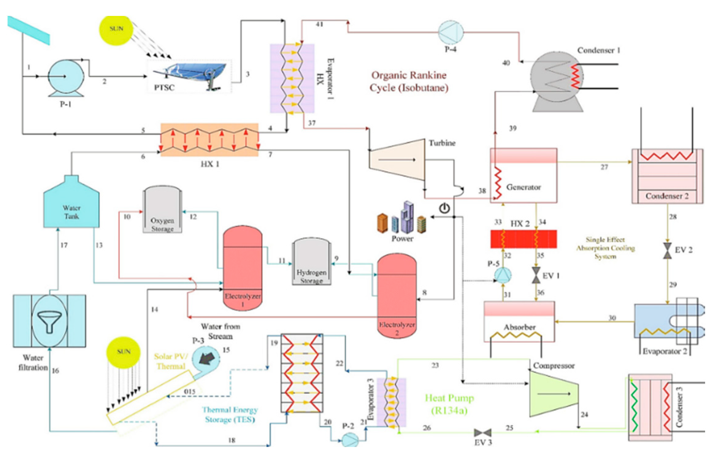
Zeng et al.[107] investigated combined multi energy system including cooling, heating and power/ground source heat pump/photovoltaic/solar thermal. Then from energy, economy and environment viewpoint, the optimization model is established for the following total thermal demand-load ratio and following total electric demand-load ratio operation strategy under different load ratio respectively. The results showed that the comprehensive performance of the coupled system in the following total electric demand-load ratio mode is better than that in the following total thermal demand-load ratio mode under different load ratio. Raja et al.[108] proposed a new hydrogen-heat co-generation system that included a parabolic trough solar collector and a solar photovoltaic/thermal collector unit. Then the thermodynamic analysis of this system was carried out. When the solar fluid outlet temperature is 477 K, the total energy and exergy efficiency of the system are 12.90% and 54.72%, respectively. The hydrogen production capacity of the parabolic tank solar collector electrolyzer can reach 8.226g/s, and that of the solar photovoltaic/thermal collector electrolyzer can reach 0.07518g/s. The schematic of a multi-generation system comprising a PTSC and solar PV/T collector is shown in the following figure.
Figure 20. The schematic of a multi-generation system comprising a PTSC and solar PV/T collector.
Preprints 71908 g020
Behzadi et al.[109] proposed and modeled an advanced solar-based building energy system, which is integrated with electricity and district heating grids. TRNSYS software was employed to do the simulations and comparative analysis of this system. The results showed that the ultralow-temperature district heating model is the most suitable case for the proposed system. The maximum overall efficiency values of 74.51%, 62.35%, and 52.35% for three different modes are achieved.

4.1.2. Experimental research

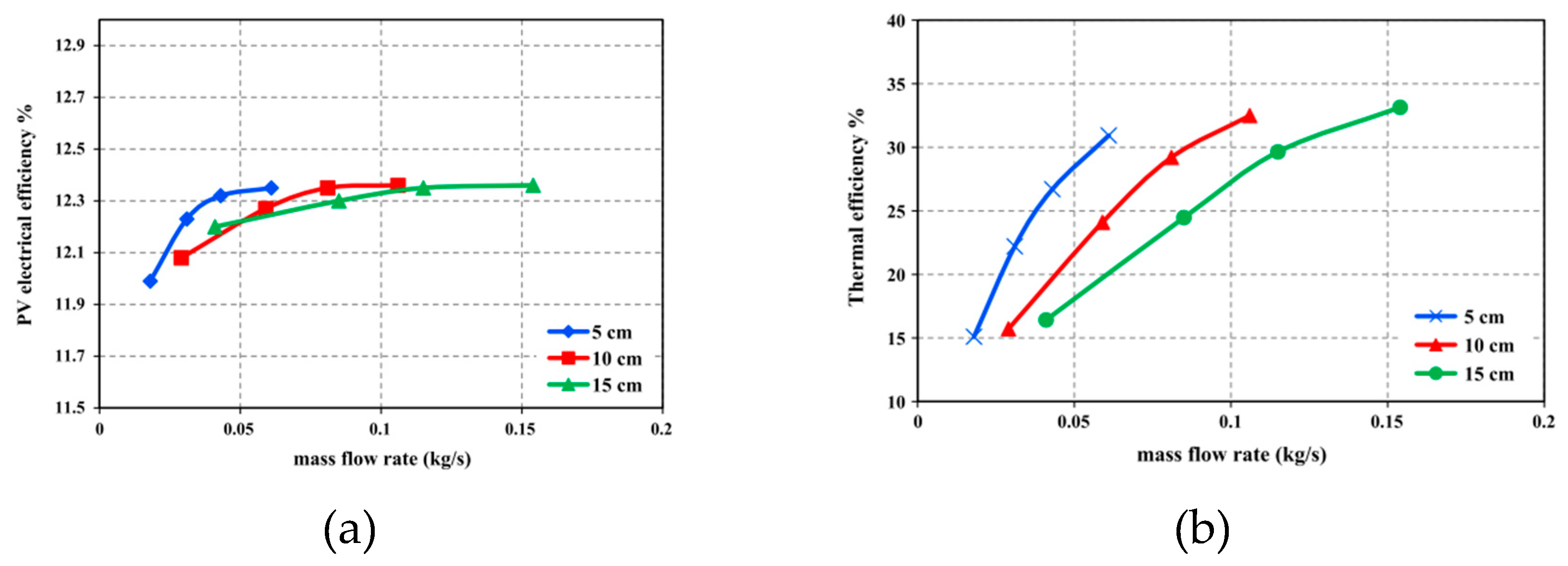
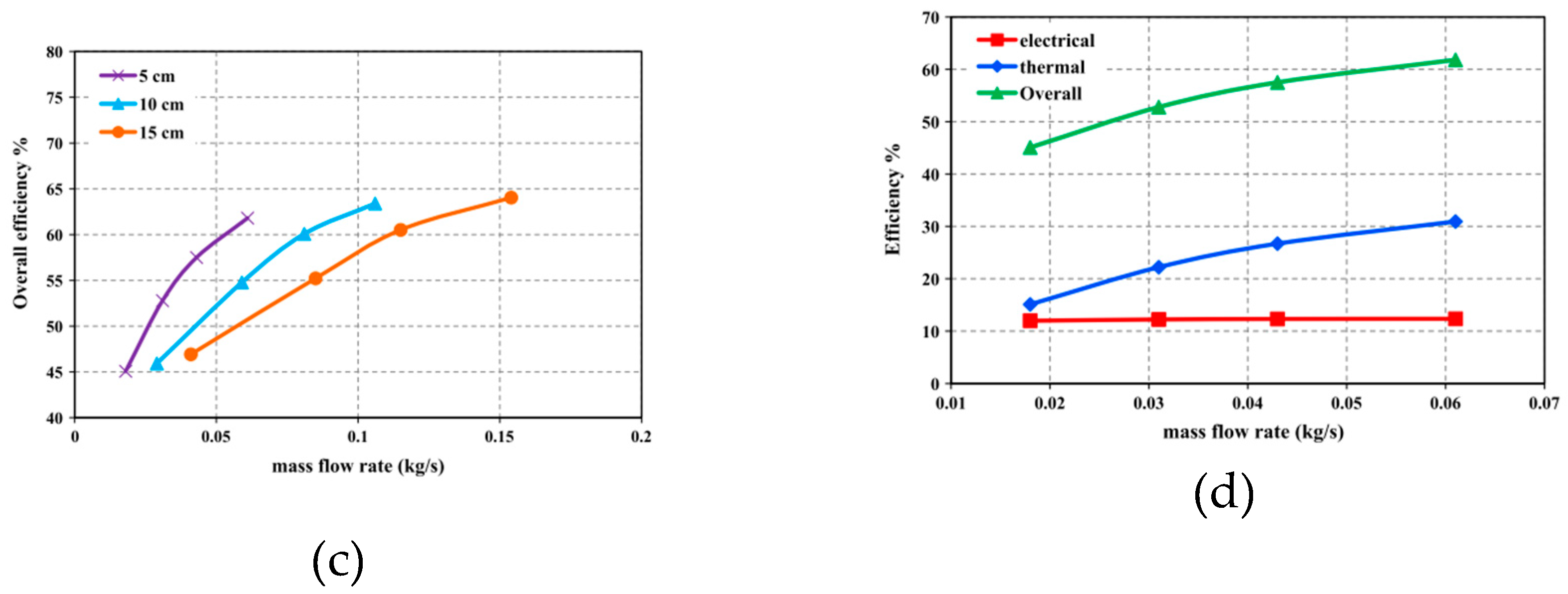
Kasaeian et al.[110] experimentally investigated the effect of forced convection on the thermal and electrical efficiency of PV/T systems. An air-cooled PVT system with four fans was tested. The influence of air quality flow rate and duct depth on system performance is studied. The results show that the increase of air mass flow and the decrease of duct depth can improve the thermal efficiency of the system, but have little effect on the electrical efficiency. The results are shown in the following figures.
Figure 21. (a) Variations of the electrical efficiency of photovoltaic panels in different channel depths versus mass flow rate; (b) Variations of the thermal efficiency of photovoltaic panels in different channel depths versus mass flow rate; (c) Variations of overall efficiency versus mass flow rate in different channel depth values; (d) Variations of electrical, thermal and overall efficiencies in the channel versus mass flow rate.
Preprints 71908 g021aPreprints 71908 g021b
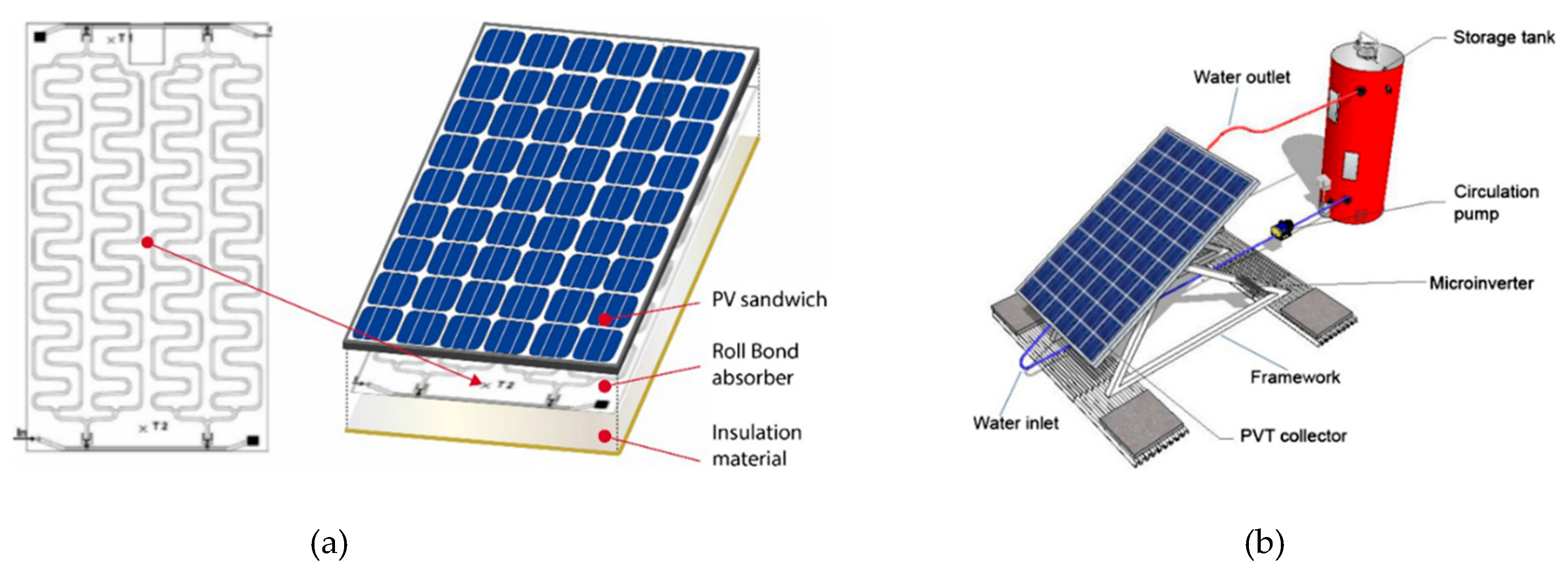
Saygin et al.[111] experimented with an improved photovoltaic/thermal (PV/T) solar collector. In the proposed model, air enters the collector through a slot in the middle of the glass cover. The system is repeatedly measured by changing the position of the photovoltaic module inside the collector and the thermoelectric performance of the solar collector. When the distance between the PV module and the overlay is 3 cm, the thermal performance is the best, and when the distance is 5 cm, the electrical performance is the best. It is also found that increasing the mass flow rate can improve the thermal performance of the system. Slimani et al.[112] modeled four types of PVTS, namely photovoltaic modules, conventional hybrid solar air collectors, glass hybrid solar air collectors and glass dual-pass hybrid solar air collectors. The simulation results of the model are verified by the previous experimental results. The numerical results show that the average daily energy efficiency of the four systems reaches 29.63%, 51.02%, 69.47% and 74%, respectively. To evaluate the effect of the tilt angle and connection mode of PVT modules on system performance, Sun et al.[113] constructed a PVT hot water system naturally driven by gravity. The dynamic simulation model of PVT hot water system is established. Compared with the parallel connection, the power of the series connection is reduced by 2.0%, the heat energy is increased by 11.4%, and the total energy is increased by 5.4%. When considering the total energy and projection length, the optimal tilt angle is 40o. Aste et al.[114] proposed a numerical model for water-PVTs, simulated and verified the model with empirical results, and tested the model for different places. The absorber plate, PVT collector configuration and PVT system configuration are shown in the following figures.
Figure 22. (a) The absorber plate and PVT collector configuration; (b) The PVT system configuration.
Preprints 71908 g022
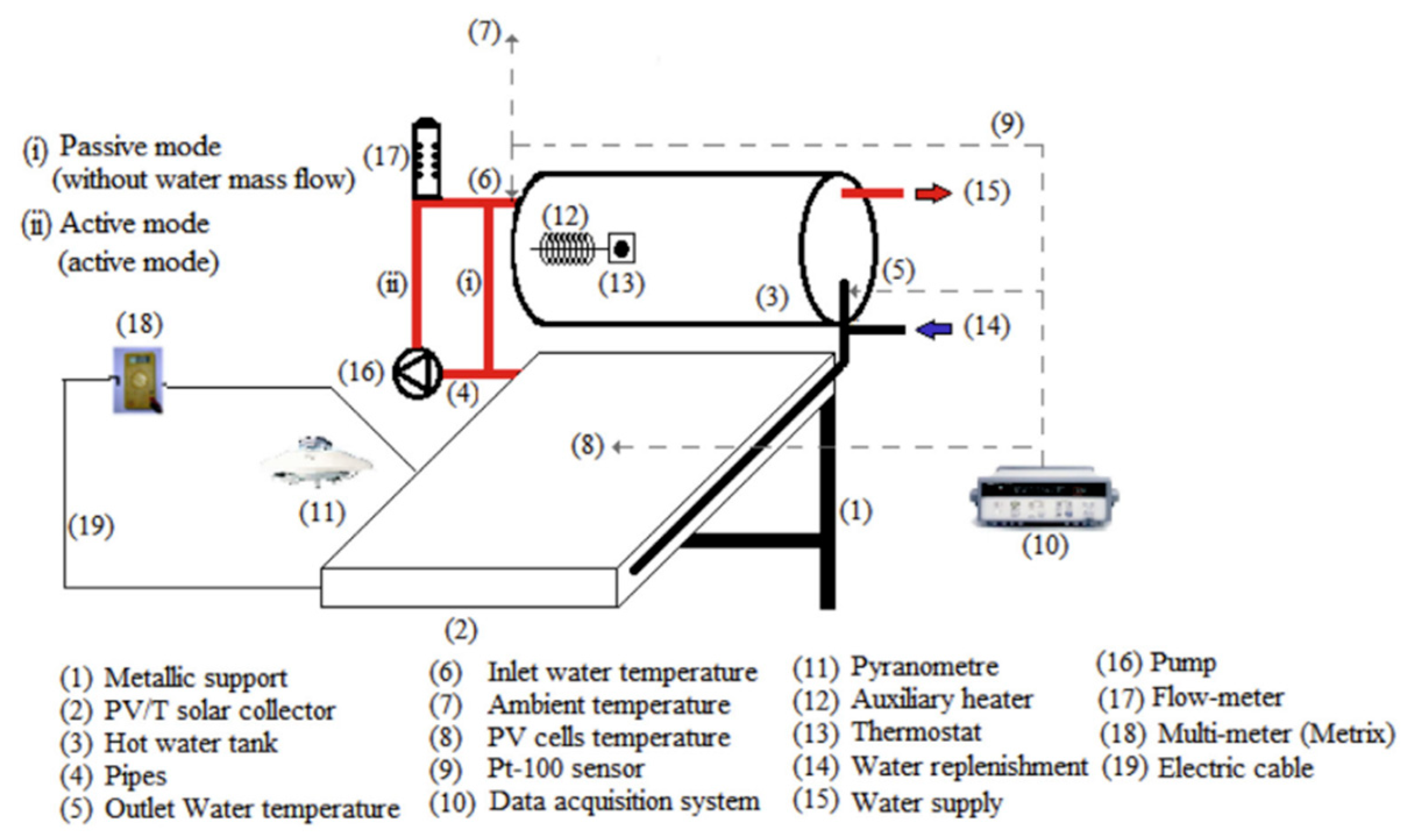
Chen et al.[115] designed a building integrated photovoltaic thermal multi-functional roof panel, which has been collecting solar energy in the form of photovoltaic power and heat energy from warm water, then tested in the room. The results showed that the photovoltaic thermal building roof integrated system can significantly improve the energy conversion efficiency of power generation and heat collection. Hazami et al.[116] conducted an outdoor experiment on the PVT system using both passive and active methods. Then, a comprehensive energy analysis and exergy analysis were carried out to evaluate this system. The results showed that the maximum values of instantaneous thermal efficiency and electrical efficiency are about 50% and 15% respectively in active mode. The maximum exergic efficiency of thermal and electrical power of the system was about 50% and 14.8%, respectively. The descriptive diagram of the experimental set-up of the PV/T solar system is shown in the figure.
Figure 23. The descriptive diagram of the experimental set-up of the PV/T solar system.
Preprints 71908 g023
Wang et al.[117] proposed a new type of PVT system to provide hot water and electricity for residents. In order to study the performance of the system, an experiment was carried out in the laboratory. It was found that when the solar radiation was 900W/m2 and the water flow rate was 600L/h, the water temperature of the tank reached a maximum of 47.23oC. When the solar radiation is 900W/m2 and the water flow rate is 600L/h, the average daily thermal efficiency, electrical efficiency and total efficiency of the system are 61.1%, 7.8% and 68.9% of the maximum value, respectively. Compared with traditional PVT systems, the cost and efficiency of the system are improved by 52% and 25.5%, respectively.

4.2. Fuel cell

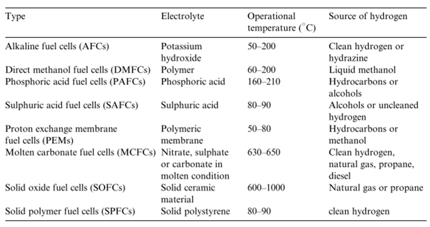
Fuel cell is a chemical device that converts the chemical energy of a fuel directly into electrical energy, so it is not limited by Carnot efficiency. As a result, it is highly efficient. From the perspective of saving energy and protecting the ecological environment, fuel cells are the most promising technology for power generation. The available fuel types are as follows: alkaline fuel cells, direct methanol fuel cells, phosphoric acid fuel cells, sulphuric acid fuel cells, proton exchange membrane fuel cells, molten carbonate fuel cells, solid oxide fuel cells, solid co-mer fuel cells[118]. The classification of fuel cells is shown in Table 11. In recent years, with the gradual maturation of fuel cell technology, fuel cells have been rapidly developed and commercialized in the high, middle and low power range, especially in CHP systems. There are currently five types of fuel cells used in CHP systems:PEMFC (proton exchange membrane fuel cells), SOFC (solid oxide fuel cells), MCFC (molten carbonate fuel cell), PAFC (phosphoric acid fuel cells), and AFC (alkaline fuel cells) [119].
Table 6. Existing fuel cell technologies.
Preprints 71908 i004

4.2.1. Optimized design parameters

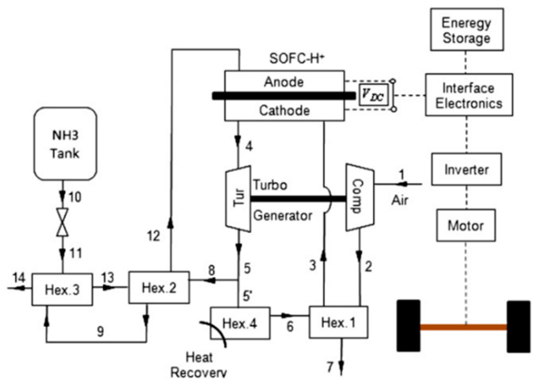
Many scholars have optimized the layout and design parameters of fuel cell-based co-generation systems to improve its efficiency. Fryda et al.[120] proposed a co-generation system based on solid oxide fuel cells. The CHP system was modeled in the Aspen Plus software, including gasification, SOFC, gas cleaning and heat pipe models. For the system with an average current density of 3000Am2, the proposed system will consume 90 kg/h biomass and generate 170 kWe net power with a system operating efficiency of 36%, of which 34% is electrical. Baniasadi et al.[121] applied a co-generation system to vehicles. The system is an ammonia powered solid oxide fuel cell based on proton conducting electrolyte, and has the function of heat recovery. The calculation results show that the energy efficiency of the system is between 40% - 60%, and the exergy efficiency is between 60% and 90%. When the average working temperature rises by 100oC, the entropy yield of the co-generation system decreases by 25%. The ammonia-fed CHP system is illustrated in Figure 24.
Arab et al.[122] analyzed a combined heat and power systems which was integrated with solid oxide fuel cell based on integrating exergy concepts, energy and mass balance equations for the first time. The electrical efficiency, total efficiency and exergetic performance coefficient of this cycle were 54%, 79% and 58%, respectively. Figure 25 shows the schematic view of a methane-fueled SOFC/CHP system with IR and anode off-gas recirculation.
Abraham et al.[123] presented a comprehensive steady state modelling and thermodynamic analysis of oxygen ion-conducting solid oxide fuel cells (SOFC-O) and hydrogen proton-conducting solid oxide fuel cells (SOFC-H). The SOFC-O based system offers better overall performance than that with the SOFC-H option mainly due to the detrimental reverse water-gas shift reaction at the SOFC anode as well as the unique configuration of the system. Gholamian et al.[124] proposed a biomass-fueled co-generation system which consists of a biomass gasifier, a SOFC, a double effect absorption refrigeration cycle and a heat recovery steam generator. Municipal solid waste is examined as biomass and it is observed that maximum exergy efficiency of this system is 37.92% with a CO2 emission of 20.37 t/(MW·h) which shows an increase of 49.88% in exergy efficiency and 64.02% decrease in CO2 emission, compared to the solo SOFC system. Au et al.[125] tried to optimize the operating temperature of molten carbonate fuel cell in the co-generation system for the first time. The maximum values of electrical efficiency and exergy efficiency are 51.9% and 58.7% at 675oC. The overall thermal efficiency of the CHP system increased from 87.1% at 600oC to 88.9% at 700oC. In general, the performance changes little within the operating temperature range of MCFC.

4.2.2. Operating status

Another issue considering when investigating fuel cell-based co-generation systems is the determination of operating status. In order to determine the cost target of fuel cell CHP, Staffell et al.[126] presented a meta-study of the current state of the art, and used with 102 house-years of demand to simulate the range of economic performance expected from four fuel cell technologies within the UK domestic CHP market. Annual savings relative to a condensing boiler are estimated at € 170-300 for a 1kWe fuel cell, giving a target cost of € 350-625 kW−1 for any fuel cell technology that can demonstrate a 2.5-year lifetime. Increasing lifetime and reducing fuel cell capacity are identified as routes to accelerated market entry. Sharkh et al.[127,128] presents a methodology for finding the optimal output power from a PEM fuel cell power plant. The technique used is based on evolutionary programming to find a near-optimal solution of the problem. The optimal operational strategy of the FCPP for different tariffs is achieved through the estimation of the following: hourly generated power, the amount of thermal power recovered, power trade with the local grid, and the quantity of hydrogen that can be produced. Results show the importance of optimizing system cost parameters in order to minimize overall operating cost. Hawkes et al.[129,130] developed a detailed techno-economic energy-cost minimization model of a micro-CHP system drawing on steady-state and dynamic SOFC stack models and power converter design. This model is applied it to identify minimum costs and optimum stack capacities under various current density change constraints. At the same time, to minimize the cost of the system, the operation strategy should consider both heat demand and power demand, rather than taking heat demand or power demand as the only dispatching signal. In order to accurately determine the size of the housing fuel cell system and predict its performance, Ferguson et al.[131] developed a steady-state model of the general co-generation based on fuel cell system. The model is applicable to (i) estimate the fuel use of the system, as well as electricity and heat production, (ii) investigate the applicability of the fuel cell system in different climates, (iii) the size of the fuel cell system and auxiliary equipment, and (iv) evaluate different control strategies.
Fuel cell cycle operating temperature is high, the output of electricity at the same time tail exhaust temperature can reach 600-1000oC. At present, the power generation efficiency of high temperature fuel cell is higher than that of traditional heat engine. In addition, FC-CHP have many advantages, such as reduction of CO2 emissions, reduction of electricity and grid independences. This technique has broad development space in the future field of distributed energy.

5. Conclusion

Co-generation is a novel system that combines advanced technology and equipment such as steam turbine, gas turbine, heat pump, and energy integrated control system. It employs a comprehensive step-by-step utilization of input energy and internal energy flow based on thermal energy level to achieve higher energy utilization while simultaneously reducing carbon dioxide and hazardous gas emissions. The current development direction of the co-generation system is mostly represented in the three aspects listed below:
High efficiency: Switching from an external combustion engine to an internal combustion engine, as well as switching from a thermal cycle to a non-thermal cycle. Fuel cells, for example, can be used as the power subsystem of cogeneration systems and combined with typical thermal cycles, or the chemical process inside the fuel cell can be integrated with the co-generation system. This can fully incorporate the integrated chemical and physical energy steps of fuel energy usage and achieve more efficient energy utilization.
Low carbon: Co-generation systems can use a variety of energy sources, including fossil energy, fossil energy supplemented by renewable energy, and renewable energy as the primary energy source. With the growing awareness of sustainable development in society, the amount of renewable energy in the entire energy system will grow, as will its application in the combined heating and power system. The intermittent and unstable nature of renewable energy is a pressing issue, and energy storage may be a viable solution.
Flexible: Traditional centralized energy supply systems use big-capacity equipment and centralized production to deliver a variety of energy to a large number of customers over a larger region via specialized transmission facilities (large power grids, huge heat networks, and so on). Nowadays, co-generation systems are more likely to face consumers directly, produce and provide energy locally based on user needs, and have numerous functions to achieve multiple objectives of medium and small energy conversion and utilization systems. The integrated energy utilization mode is used to achieve a variety of energy supply goals, including increased energy utilization, lower energy costs, increased energy security, and improved environmental performance.

Author Contributions

Conceptualization, W.M., W.H., Q.L. and G.X.; validation, W.H., Q.L. and G.X.; investigation, W.M.; writing—original draft preparation, W.M. and W.H.; writing—review and editing, W.M. and W.H. All authors have read and agreed to the published version of the manuscript.”

Funding

This work was funded by the National Science and Technology Major Project of China (J2019-I-0009-0009) and the National Natural Science Foundation of China (No.52006213).

Data Availability Statement

Not applicable.

Conflicts of Interest

The authors declare no conflict of interest.

References

  1. Tian, H.; Liu, P. Challenges and opportunities of Rankine cycle for waste heat recovery from internal combustion engine. Progress in Energy and Combustion Science 2021, 84. [Google Scholar] [CrossRef]
  2. Bhattacharya, M.; Paramati, S. R. The effect of renewable energy consumption on economic growth: Evidence from top 38 countries. Applied Energy 2016, 162, 733–741. [Google Scholar] [CrossRef]
  3. Fan, X. c.; Wang, W. q. Analysis and countermeasures of wind power curtailment in China. Renewable and Sustainable Energy Reviews 2015, 52, 1429–1436. [Google Scholar] [CrossRef]
  4. Rosen, M. A. Energy, environmental, health and cost benefits of cogeneration from fossil fuels and nuclear energy using the electrical utility facilities of a province. Energy for Sustainable Development 2009, 13, (1), 43–51. [Google Scholar] [CrossRef]
  5. Wang, L.; Chen, Y. h. Reconstruction scheme and test analysis for heating supply with high back pressure of a 300MW unit. Turbine Technology 2018, 60, 385–388. [Google Scholar]
  6. Tian, S.; Wang, S. Research on energy saving reconstruction technology of 330MW air cooling unit. Energy Conservation 2016, 35, 72–74. [Google Scholar]
  7. ZHang, P.; Yang, T. The Economy Analysis of the High Back Pressure Heating Technology on Direct Air-colled Unit. Turbine Technology 2014, 56, (03), 209–212. [Google Scholar]
  8. Gong, X. M.; Cui, H. P. Analysis on operation characteristics of high back-pressure heating for large air-cooling units. Thermal Power Generation 2018, 47, (08), 103–109. [Google Scholar]
  9. Li, Y.; Mi, P. Full operating conditions optimization study of new co-generation heating system based on waste heat utilization of exhausted steam. Energy Conversion and Management 2018, 155, 91–99. [Google Scholar] [CrossRef]
  10. Zhang, H. S.; Zhao, H. B. Performance analysis of the coal-fired power plant with combined heat and power (CHP) based on absorption heat pumps. Journal of the Energy Institute 2016, 89, (1), 70–80. [Google Scholar] [CrossRef]
  11. Sun, F.; Fu, L. A new waste heat district heating system with combined heat and power (CHP) based on ejector heat exchangers and absorption heat pumps. Energy 2014, 69, 516–524. [Google Scholar] [CrossRef]
  12. Ommen, T.; Markussen, W. B. Heat pumps in combined heat and power systems. Energy 2014, 76, 989–1000. [Google Scholar] [CrossRef]
  13. Liang, Y.; Shu, G. Investigation of a cascade waste heat recovery system based on coupling of steam Rankine cycle and NH3-H2O absorption refrigeration cycle. Energy Conversion and Management 2018, 166, 697–703. [Google Scholar] [CrossRef]
  14. Cho, H.; Sarwar, R. Design and feasibility study of combined heat and power systems integrated with heat pump. Applied Thermal Engineering 2016, 93, 155–165. [Google Scholar] [CrossRef]
  15. Sun, J.; Fu, L. Experimental study of heat exchanger basing on absorption cycle for CHP system. Applied Thermal Engineering 2016, 102, 1280–1286. [Google Scholar] [CrossRef]
  16. Wang, X.; Zhao, X. Entransy analysis of secondary network flow distribution in absorption heat exchanger. Energy 2018, 147, 428–439. [Google Scholar] [CrossRef]
  17. Xie, X.; Jiang, Y. Absorption heat exchangers for long-distance heat transportation. Energy 2017, 141, 2242–2250. [Google Scholar] [CrossRef]
  18. Wu, W.; Wang, B. Absorption heating technologies: A review and perspective. Applied Energy 2014, 130, 51–71. [Google Scholar] [CrossRef]
  19. Sun, J.; Fu, L. A review of working fluids of absorption cycles. Renewable and Sustainable Energy Reviews 2012, 16, (4), 1899–1906. [Google Scholar] [CrossRef]
  20. Liu, S.; ZHeng, L. J. Analysis on heating supply retrofit of a 200 MW unit by cutting off the low-pressure cylinder steam admission. Huadian Technology 2020, 42, (06), 76–82. [Google Scholar]
  21. Li, S. M.; Liu, Q. S. Flexibility Transformation Analysis of 350 MW Supercritical Cogeneration Unit. Power Generation Technology 2018, 39, (05), 449–454. [Google Scholar]
  22. Guo, R. H.; Wang, L. P. Research and application of low pressure rotor optical shaft heating for 200MW pure condensing Unit. Resource Conservation and Environmental Protection 2019, 209, (04), 3–5. [Google Scholar]
  23. Yang, L.; Liu, Y. L. Operation optimization of cogeneration unit equipped with heat accumulator. Thermal Power Generation 2020, 49, (04), 70–76. [Google Scholar]
  24. Salpakari, J.; Mikkola, J. Improved flexibility with large-scale variable renewable power in cities through optimal demand side management and power-to-heat conversion. Energy Conversion and Management 2016, 126, 649–661. [Google Scholar] [CrossRef]
  25. Hedegaard, K.; Münster, M. Influence of individual heat pumps on wind power integration-Energy system investments and operation. Energy Conversion and Management 2013, 75, 673–684. [Google Scholar] [CrossRef]
  26. Mathiesen, B. V.; Lund, H. Comparative analyses of seven technologies to facilitate the integration of fluctuating renewable energy sources. IET Renewable Power Generation 2009, 3, (2).
  27. Wang, L.; Chen, X. Contribution from urban heating to China's 2020 goal of emission reduction. Environ Sci Technol 2011, 45, (11), 4676–81. [Google Scholar] [CrossRef]
  28. ZOSCHAK, R. J.; Wu, S. F. Studies of the direct input of solar energy to a fossil-fueled central station steam power plant. Solar Energy 1975, 17, 297–305. [Google Scholar] [CrossRef]
  29. Hu, E.; Yang, Y. Solar thermal aided power generation. Applied Energy 2010, 87, (9), 2881–2885. [Google Scholar] [CrossRef]
  30. Yang, Y.; Yan, Q. An efficient way to use medium-or-low temperature solar heat for power generation-integration into conventional power plant. Applied Thermal Engineering 2011, 31, (2-3), 157-162.
  31. Popov, D. An option for solar thermal repowering of fossil fuel fired power plants. Solar Energy 2011, 85, (2), 344–349. [Google Scholar] [CrossRef]
  32. Zhang, M.; Du, X. Performance of double source boiler with coal-fired and solar power tower heat for supercritical power generating unit. Energy 2016, 104, 64–75. [Google Scholar] [CrossRef]
  33. Zhu, Y.; Zhai, R. Exergy destruction analysis of solar tower aided coal-fired power generation system using exergy and advanced exergetic methods. Applied Thermal Engineering 2016, 108, 339–346. [Google Scholar] [CrossRef]
  34. Li, P.; Nord, N. Integrated multiscale simulation of combined heat and power based district heating system. Energy Conversion and Management 2015, 106, 337–354. [Google Scholar] [CrossRef]
  35. Ziębik, A.; Budnik, M. Thermodynamic indices assessing the integration of coal-fired CHP plants with post-combustion CO2 processing units (CPU). Energy Conversion and Management 2013, 73, 389–397. [Google Scholar] [CrossRef]
  36. Bhuiyan, A. A.; Blicblau, A. S. A review on thermo-chemical characteristics of coal/biomass co-firing in industrial furnace. Journal of the Energy Institute 2018, 91, (1), 1–18. [Google Scholar] [CrossRef]
  37. Luo, Y. Z. Analysis on commercialization prospect of straw power generation. Research and Approach 2005, 27, (03), 43–45. [Google Scholar]
  38. McIlveen Wright, D. R.; Huang, Y. A technical and environmental analysis of co-combustion of coal and biomass in fluidised bed technologies. Fuel 2007, 86, (14), 2032–2042. [Google Scholar] [CrossRef]
  39. Kastanaki, E.; Vamvuka, D. Thermogravimetric studies of the behavior of lignite–biomass blends during devolatilization. Fuel Processing Technology 2002, 77-78, 159-166.
  40. Vamvuka, D.; Kakaras, E. Pyrolysis characteristics and kinetics of biomass residuals mixtures with lignite. Fuel 2003, 82, (15-17), 1949-1960.
  41. Chen, H.; Goswami, D. Y. A review of thermodynamic cycles and working fluids for the conversion of low-grade heat. Renewable and Sustainable Energy Reviews 2010, 14, (9), 3059–3067. [Google Scholar] [CrossRef]
  42. Lecompte, S.; Huisseune, H. Review of organic Rankine cycle (ORC) architectures for waste heat recovery. Renewable and Sustainable Energy Reviews 2015, 47, 448–461. [Google Scholar] [CrossRef]
  43. Tchanche, B. F.; Lambrinos, G. Low-grade heat conversion into power using organic Rankine cycles-A review of various applications. Renewable and Sustainable Energy Reviews 2011, 15, (8), 3963–3979. [Google Scholar] [CrossRef]
  44. Soltani, R.; Dincer, I. Thermodynamic analysis of a novel multigeneration energy system based on heat recovery from a biomass CHP cycle. Applied Thermal Engineering 2015, 89, 90–100. [Google Scholar] [CrossRef]
  45. Karellas, S.; Braimakis, K. Energy-exergy analysis and economic investigation of a cogeneration and trigeneration ORC–VCC hybrid system utilizing biomass fuel and solar power. Energy Conversion and Management 2016, 107, 103–113. [Google Scholar] [CrossRef]
  46. Boyaghchi, F. A.; Chavoshi, M. Monthly assessments of exergetic, economic and environmental criteria and optimization of a solar micro-CCHP based on DORC. Solar Energy 2018, 166, 351–370. [Google Scholar] [CrossRef]
  47. Montazerinejad, H.; Ahmadi, P. Advanced exergy, exergo-economic and exrgo-environmental analyses of a solar based trigeneration energy system. Applied Thermal Engineering 2019, 152, 666–685. [Google Scholar] [CrossRef]
  48. Al Sulaiman, F. A.; Dincer, I. Exergy modeling of a new solar driven trigeneration system. Solar Energy 2011, 85, (9), 2228–2243. [Google Scholar] [CrossRef]
  49. Freeman, J.; Hellgardt, K. An assessment of solar-powered organic Rankine cycle systems for combined heating and power in UK domestic applications. Applied Energy 2015, 138, 605–620. [Google Scholar] [CrossRef]
  50. Uday Kumar, N. T.; Mohan, G. Performance analysis of solar cogeneration system with different integration strategies for potable water and domestic hot water production. Applied Energy 2016, 170, 466–475. [Google Scholar] [CrossRef]
  51. Javan, S.; Mohamadi, V. Fluid selection optimization of a combined cooling, heating and power (CCHP) system for residential applications. Applied Thermal Engineering 2016, 96, 26–38. [Google Scholar] [CrossRef]
  52. Kang, S.; Lu, L. A Novel CHP-HP Coupling System and its Optimization Analysis by Genetic Algorithm. Energy Procedia 2017, 105, 2089–2094. [Google Scholar] [CrossRef]
  53. Ozlu, S.; Dincer, I. Performance assessment of a new solar energy-based multigeneration system. Energy 2016, 112, 164–178. [Google Scholar] [CrossRef]
  54. Ahmadi, P.; Dincer, I. Exergo-environmental analysis of an integrated organic Rankine cycle for trigeneration. Energy Conversion and Management 2012, 64, 447–453. [Google Scholar] [CrossRef]
  55. Mago, P. J.; Hueffed, A. Analysis and optimization of the use of CHP-ORC systems for small commercial buildings. Energy and Buildings 2010, 42, (9), 1491–1498. [Google Scholar] [CrossRef]
  56. Wang, M.; Wang, J. Multi-objective optimization of a combined cooling, heating and power system driven by solar energy. Energy Conversion and Management 2015, 89, 289–297. [Google Scholar] [CrossRef]
  57. Thombare, D. G.; Verma, S. K. Technological development in the Stirling cycle engines. Renewable and Sustainable Energy Reviews 2008, 12, (1), 1–38. [Google Scholar] [CrossRef]
  58. Zare, S.; Tavakolpour saleh, A. R. Design and optimization of Stirling engines using soft computing methods: A review. Applied Energy 2021, 283. [Google Scholar] [CrossRef]
  59. Ferreira, A. C.; Silva, J. Assessment of the Stirling engine performance comparing two renewable energy sources: Solar energy and biomass. Renewable Energy 2020, 154, 581–597. [Google Scholar] [CrossRef]
  60. Salehi, A.; Mousavi, S. M. Energy, exergy, and environmental (3E) assessments of an integrated molten carbonate fuel cell (MCFC), Stirling engine and organic Rankine cycle (ORC) cogeneration system fed by a biomass-fueled gasifier. International Journal of Hydrogen Energy 2019, 44, (59), 31488–31505. [Google Scholar] [CrossRef]
  61. Damirchi, H.; Najafi, G. Micro Combined Heat and Power to provide heat and electrical power using biomass and Gamma-type Stirling engine. Applied Thermal Engineering 2016, 103, 1460–1469. [Google Scholar] [CrossRef]
  62. Cardozo, E.; Erlich, C. Integration of a wood pellet burner and a Stirling engine to produce residential heat and power. Applied Thermal Engineering 2014, 73, (1), 671–680. [Google Scholar] [CrossRef]
  63. Chen, J.; Li, X. Energetic, economic, and environmental assessment of a Stirling engine based gasification CCHP system. Applied Energy 2021, 281. [Google Scholar] [CrossRef]
  64. Najafi, G.; Hoseini, S. S. Optimization of combustion in micro combined heat and power (mCHP) system with the biomass-Stirling engine using SiO2 and Al2O3 nanofluids. Applied Thermal Engineering 2020, 169. [Google Scholar] [CrossRef]
  65. Udeh, G. T.; Michailos, S. A techno-enviro-economic assessment of a biomass fuelled micro-CCHP driven by a hybrid Stirling and ORC engine. Energy Conversion and Management 2021, 227. [Google Scholar] [CrossRef]
  66. Arashnia, I.; Najafi, G. Development of Micro-scale Biomass-fuelled CHP System Using Stirling Engine. Energy Procedia 2015, 75, 1108–1113. [Google Scholar] [CrossRef]
  67. Laing, D.; Trabing, C. Second generation sodium heat pipe receiver for a USAB V-160 stirling engine:evaluation of on-sun test results using the proposed IEA guidelines and analysis of heat pipe damage. Journal of Solar Energy Engineering 1997, 119, 279–285. [Google Scholar] [CrossRef]
  68. Laing, D.; Palsson, M. Hybrid dish/stirling systems: combustor and heat pipe receiver development. Journal of Solar Energy Engineering 2002, 124, 176–181. [Google Scholar] [CrossRef]
  69. Moghadam, R. S.; Sayyaadi, H. Sizing a solar dish Stirling micro-CHP system for residential application in diverse climatic conditions based on 3E analysis. Energy Conversion and Management 2013, 75, 348–365. [Google Scholar] [CrossRef]
  70. Babaelahi, M.; Jafari, H. Analytical design and optimization of a new hybrid solar-driven micro gas turbine/stirling engine, based on exergo-enviro-economic concept. Sustainable Energy Technologies and Assessments 2020, 42. [Google Scholar] [CrossRef]
  71. Wang, Z.; Han, W. Proposal and assessment of a new CCHP system integrating gas turbine and heat-driven cooling/power cogeneration. Energy Conversion and Management 2017, 144, 1–9. [Google Scholar] [CrossRef]
  72. Krewinkel, R. A review of gas turbine effusion cooling studies. International Journal of Heat and Mass Transfer 2013, 66, 706–722. [Google Scholar] [CrossRef]
  73. Rian, A. B.; Ertesvåg, I. S. Exergy Evaluation of the Arctic Snøhvit Liquefied Natural Gas Processing Plant in Northern Norway-Significance of Ambient Temperature. Energy and Fuels 2012, 26, (2), 1259–1267. [Google Scholar] [CrossRef]
  74. Yoru, Y.; Karakoc, T. H. Dynamic energy and exergy analyses of an industrial cogeneration system. International Journal of Energy Research 2010, 34, (4), 345–356. [Google Scholar] [CrossRef]
  75. Ahmadi, P.; Almasi, A. Multi-objective optimization of a combined heat and power (CHP) system for heating purpose in a paper mill using evolutionary algorithm. International Journal of Energy Research 2012, 36, (1), 46–63. [Google Scholar] [CrossRef]
  76. Yang, B.; CHen, L. Exergy performance analyses of an irreversible two-stage intercooled regenerative reheated closed Brayton CHP plant. Int. J. Exergy 2014, 4, (4), 459–483. [Google Scholar] [CrossRef]
  77. Hou, S.; Zhang, F. Optimization of a combined cooling, heating and power system using CO2 as main working fluid driven by gas turbine waste heat. Energy Conversion and Management 2018, 178, 235–249. [Google Scholar] [CrossRef]
  78. Maghanki, M. M.; Ghobadian, B. Micro combined heat and power (MCHP) technologies and applications. Renewable and Sustainable Energy Reviews 2013, 28, 510–524. [Google Scholar] [CrossRef]
  79. Balli, O.; Aras, H. Energetic and exergetic performance evaluation of a combined heat and power system with the micro gas turbine (MGTCHP). International Journal of Energy Research 2007, 31, (14), 1425–1440. [Google Scholar] [CrossRef]
  80. Haydar, A.; Ozgur, B. Exergoeconomic Analysis of a Combined Heat and Power System with the Micro Gas Turbine (MGTCHP). Energy Exploration and Exploitation 2008, 26, (1), 53–70. [Google Scholar]
  81. Campos-Celador, Á.; Pérez-Iribarren, E. Thermoeconomic analysis of a micro-CHP installation in a tertiary sector building through dynamic simulation. Energy 2012, 45, (1), 228–236. [Google Scholar] [CrossRef]
  82. Thu, K.; Saha, B. B. Thermodynamic analysis on the part-load performance of a microturbine system for micro/mini-CHP applications. Applied Energy 2016, 178, 600–608. [Google Scholar] [CrossRef]
  83. Pirkandi, J.; Jokar, M. A. Simulation and multi-objective optimization of a combined heat and power (CHP) system integrated with low-energy buildings. Journal of Building Engineering 2016, 5, 13–23. [Google Scholar] [CrossRef]
  84. Lei, H.; Han, D. Study on different heat supplementation strategies for a combined cooling, heating and power system. Applied Thermal Engineering 2018, 144, 558–570. [Google Scholar] [CrossRef]
  85. Campos Celador, A.; Odriozola, M. Implications of the modelling of stratified hot water storage tanks in the simulation of CHP plants. Energy Conversion and Management 2011, 52, (8-9), 3018-3026.
  86. Ehyaei, M. A.; Ahmadi, P. Feasibility study of applying internal combustion engines in residential buildings by exergy, economic and environmental analysis. Energy and Buildings 2012, 55, 405–413. [Google Scholar] [CrossRef]
  87. Yingjian, L.; Qi, Q. Energy balance and efficiency analysis for power generation in internal combustion engine sets using biogas. Sustainable Energy Technologies and Assessments 2014, 6, 25–33. [Google Scholar] [CrossRef]
  88. Rovas, D.; Zabaniotou, A. Exergy analysis of a small gasification-ICE integrated system for CHP production fueled with Mediterranean agro-food processing wastes: The SMARt-CHP. Renewable Energy 2015, 83, 510–517. [Google Scholar] [CrossRef]
  89. Darzi, M.; Johnson, D. Gaseous fuels variation effects on first and second law analyses of a small direct injection engine for micro-CHP systems. Energy Conversion and Management 2019, 184, 609–625. [Google Scholar] [CrossRef]
  90. Yildirim, U.; Gungor, A. An application of exergoeconomic analysis for a CHP system. International Journal of Electrical Power and Energy Systems 2012, 42, (1), 250–256. [Google Scholar] [CrossRef]
  91. Goyal, R.; Sharma, D. Performance and emission analysis of CI engine operated micro-trigeneration system for power, heating and space cooling. Applied Thermal Engineering 2015, 75, 817–825. [Google Scholar] [CrossRef]
  92. Aliehyaei, M.; Atabi, F. Exergy, Economic and Environmental Analysis for Simple and Combined Heat and Power IC Engines. Sustainability 2015, 7, (4), 4411–4424. [Google Scholar] [CrossRef]
  93. Taie, Z.; West, B. Detailed thermodynamic investigation of an ICE-driven, natural gas-fueled, 1 kWe micro-CHP generator. Energy Conversion and Management 2018, 166, 663–673. [Google Scholar] [CrossRef]
  94. Deng, J.; Wang, R. Z. A review of thermally activated cooling technologies for combined cooling, heating and power systems. Progress in Energy and Combustion Science 2011, 37, (2), 172–203. [Google Scholar] [CrossRef]
  95. Liu, M.; Zhang, N. Proposal and analysis of a novel ammonia-water cycle for power and refrigeration cogeneration. Energy 2007, 32, (6), 961–970. [Google Scholar] [CrossRef]
  96. Zhang, N.; Lior, N. Methodology for thermal design of novel combined refrigeration/power binary fluid systems. International Journal of Refrigeration 2007, 30, (6), 1072–1085. [Google Scholar] [CrossRef]
  97. Liu, M. Study on integrated power/refrigeration system and low CO2 emission power system with LNG cryogenic energy utilization. Doctor, Universigy of Chinese Academy of Sciences, China, 2008.
  98. CHen, Y.; Han, W. A new refrigeration system for low-temperature applications based on the power/refrigeration cycle coupling. Journal of engineering thermophysics 2015, 36, (10), 2077–2082. [Google Scholar]
  99. Sun, L. L. Mechanism and system integration study on power/cooling cogeneration cycle using waste heat. Doctor, Universigy of Chinese Academy of Sciences, China, 2013.
  100. Kasaeian, A.; Bellos, E. Solar-driven polygeneration systems: Recent progress and outlook. Applied Energy 2020, 264. [Google Scholar] [CrossRef]
  101. Bianchini, A.; Guzzini, A. Photovoltaic/thermal (PV/T) solar system: Experimental measurements, performance analysis and economic assessment. Renewable Energy 2017, 111, 543–555. [Google Scholar] [CrossRef]
  102. Charalambous, P. G.; Maidment, G. G. Photovoltaic thermal (PV/T) collectors: A review. Applied Thermal Engineering 2007, 27, (2-3), 275-286.
  103. Kasaeian, A.; Eshghi, A. T. A review on the applications of nanofluids in solar energy systems. Renewable and Sustainable Energy Reviews 2015, 43, 584–598. [Google Scholar] [CrossRef]
  104. Azizipanah-Abarghooee, R.; Niknam, T. Coordination of combined heat and power-thermal-wind-photovoltaic units in economic load dispatch using chance-constrained and jointly distributed random variables methods. Energy 2015, 79, 50–67. [Google Scholar] [CrossRef]
  105. Vorobiev, Y. V.; González-Hernández, J. Analysis of Potential Conversion Efficiency of a Solar Hybrid System With High-Temperature Stage. Journal of Solar Energy Engineering 2006, 128, (2), 258–260. [Google Scholar] [CrossRef]
  106. Akrami, E.; Gholami, A. Integrated an innovative energy system assessment by assisting solar energy for day and night time power generation: Exergetic and Exergo-economic investigation. Energy Conversion and Management 2018, 175, 21–32. [Google Scholar] [CrossRef]
  107. Zeng, R.; Zhang, X. Optimization and performance comparison of combined cooling, heating and power/ground source heat pump/photovoltaic/solar thermal system under different load ratio for two operation strategies. Energy Conversion and Management 2020, 208. [Google Scholar] [CrossRef]
  108. Raja, A. A.; Huang, Y. Novel parabolic trough solar collector and solar photovoltaic/thermal hybrid system for multi-generational systems. Energy Conversion and Management 2020, 211. [Google Scholar] [CrossRef]
  109. Behzadi, A.; Arabkoohsar, A. Comparative performance assessment of a novel cogeneration solar-driven building energy system integrating with various district heating designs. Energy Conversion and Management 2020, 220. [Google Scholar] [CrossRef]
  110. Kasaeian, A.; Khanjari, Y. Effects of forced convection on the performance of a photovoltaic thermal system: An experimental study. Experimental Thermal and Fluid Science 2017, 85, 13–21. [Google Scholar] [CrossRef]
  111. Saygin, H.; Nowzari, R. Performance evaluation of a modified PV/T solar collector: A case study in design and analysis of experiment. Solar Energy 2017, 141, 210–221. [Google Scholar] [CrossRef]
  112. Slimani, M. E. A.; Amirat, M. A detailed thermal-electrical model of three photovoltaic/thermal (PV/T) hybrid air collectors and photovoltaic (PV) module: Comparative study under Algiers climatic conditions. Energy Conversion and Management 2017, 133, 458–476. [Google Scholar] [CrossRef]
  113. Sun, L. L.; Li, M. Effect of tilt angle and connection mode of PVT modules on the energy efficiency of a hot water system for high-rise residential buildings. Renewable Energy 2016, 93, 291–301. [Google Scholar] [CrossRef]
  114. Aste, N.; Del Pero, C. Performance monitoring and modeling of an uncovered photovoltaic-thermal (PVT) water collector. Solar Energy 2016, 135, 551–568. [Google Scholar] [CrossRef]
  115. Chen, F.; Yin, H. Fabrication and laboratory-based performance testing of a building-integrated photovoltaic-thermal roofing panel. Applied Energy 2016, 177, 271–284. [Google Scholar] [CrossRef]
  116. Hazami, M.; Riahi, A. Energetic and exergetic performances analysis of a PV/T (photovoltaic thermal) solar system tested and simulated under to Tunisian (North Africa) climatic conditions. Energy 2016, 107, 78–94. [Google Scholar] [CrossRef]
  117. Wang, Z.; Zhang, J. Experimental investigation of the performance of the novel HP-BIPV/T system for use in residential buildings. Energy and Buildings 2016, 130, 295–308. [Google Scholar] [CrossRef]
  118. Boudghene Stambouli, A.; Traversa, E. Fuel cells, an alternative to standard sources of energy. Renewable and Sustainable Energy Reviews 2002, 6, 297–306. [Google Scholar] [CrossRef]
  119. Yang, Y.; Zhang, H. Multi-objective optimization for efficient modeling and improvement of the high temperature PEM fuel cell based Micro-CHP system. International Journal of Hydrogen Energy 2020, 45, (11), 6970–6981. [Google Scholar] [CrossRef]
  120. Fryda, L.; Panopoulos, K. D. Exergetic analysis of solid oxide fuel cell and biomass gasification integration with heat pipes. Energy 2008, 33, (2), 292–299. [Google Scholar] [CrossRef]
  121. Baniasadi, E.; Dincer, I. Energy and exergy analyses of a combined ammonia-fed solid oxide fuel cell system for vehicular applications. International Journal of Hydrogen Energy 2011, 36, (17), 11128–11136. [Google Scholar] [CrossRef]
  122. Arab, G.; Ghadamian, H. Thermo-economic modeling of an atmospheric SOFC/CHP cycle: an exergy based approach. Mechanics and Industry 2014, 15, (2), 113–121. [Google Scholar] [CrossRef]
  123. Abraham, F.; Dincer, I. Thermodynamic analysis of Direct Urea Solid Oxide Fuel Cell in combined heat and power applications. Journal of Power Sources 2015, 299, 544–556. [Google Scholar] [CrossRef]
  124. Gholamian, E.; Zare, V. Integration of biomass gasification with a solid oxide fuel cell in a combined cooling, heating and power system: A thermodynamic and environmental analysis. International Journal of Hydrogen Energy 2016, 41, (44), 20396–20406. [Google Scholar] [CrossRef]
  125. Au, S. F.; McPhail, S. J. The influence of operating temperature on the efficiency of a combined heat and power fuel cell plant. Journal of Power Sources 2003, 122, (1), 37–46. [Google Scholar] [CrossRef]
  126. Staffell, I.; Green, R. Cost targets for domestic fuel cell CHP. Journal of Power Sources 2008, 181, (2), 339–349. [Google Scholar] [CrossRef]
  127. El-Sharkh, M. Y.; Rahman, A. Evolutionary programming-based methodology for economical output power from PEM fuel cell for micro-grid application. Journal of Power Sources 2005, 139, (1-2), 165-169.
  128. El-Sharkh, M. Y.; Tanrioven, M. Cost related sensitivity analysis for optimal operation of a grid-parallel PEM fuel cell power plant. Journal of Power Sources 2006, 161, (2), 1198–1207. [Google Scholar] [CrossRef]
  129. Hawkes, A. D.; Aguiar, P. Techno-economic modelling of a solid oxide fuel cell stack for micro combined heat and power. Journal of Power Sources 2006, 156, (2), 321–333. [Google Scholar] [CrossRef]
  130. Hawkes, A.; Leach, M. Cost-effective operating strategy for residential micro-combined heat and power. Energy 2007, 32, (5), 711–723. [Google Scholar] [CrossRef]
  131. Ferguson, A.; Ismet Ugursal, V. Fuel cell modelling for building cogeneration applications. Journal of Power Sources 2004, 137, (1), 30–42. [Google Scholar] [CrossRef]
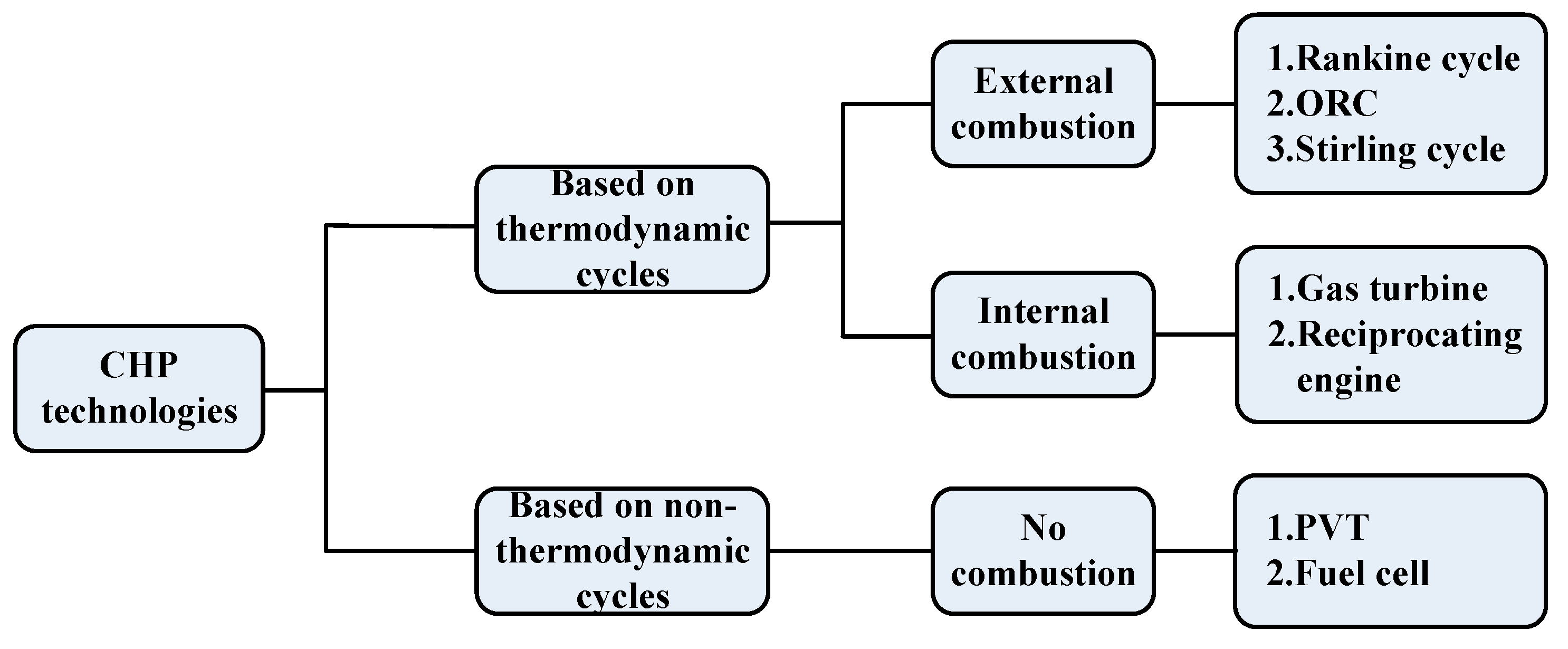
Figure 1. The logical notion block diagram.
Preprints 71908 g001
Figure 2. Schematic diagram of the retrofit solution.
Preprints 71908 g002
Figure 3. Flow sheet of the CHP system with absorption heat pump recovering waste heat.
Preprints 71908 g003
Figure 4. The schematic diagram of the novel ECCS.
Preprints 71908 g004
Figure 5. The schematic diagram of integration with solar-thermal energy in power plant.
Preprints 71908 g005
Figure 13. The sketch of the CHP plant.
Preprints 71908 g013
Figure 14. The T-S diagram for the co-generation cycle process.
Preprints 71908 g014
Figure 15. The schematic representation of micro gas turbine CHP.
Preprints 71908 g015
Figure 18. The schematic diagram of the new absorption-compression refrigeration system.
Preprints 71908 g018
Figure 24. The CHP-SOFC-H+ system configuration.
Preprints 71908 g024
Figure 25. A schematic view of a methane-fueled SOFC/CHP system with IR and anode off-gas recirculation.
Preprints 71908 g025
Disclaimer/Publisher’s Note: The statements, opinions and data contained in all publications are solely those of the individual author(s) and contributor(s) and not of MDPI and/or the editor(s). MDPI and/or the editor(s) disclaim responsibility for any injury to people or property resulting from any ideas, methods, instructions or products referred to in the content.
Copyright: This open access article is published under a Creative Commons CC BY 4.0 license, which permit the free download, distribution, and reuse, provided that the author and preprint are cited in any reuse.
Prerpints.org logo

Preprints.org is a free preprint server supported by MDPI in Basel, Switzerland.

Subscribe

© 2024 MDPI (Basel, Switzerland) unless otherwise stated