Preprint
Article

Hydrogenation of CO2 to Valuable C2-C5 Hydrocarbons on Mn-Promoted High Surface Area Iron Catalysts

Altmetrics

Downloads

220

Views

144

Comments

0

A peer-reviewed article of this preprint also exists.

Submitted:

25 April 2023

Posted:

26 April 2023

You are already at the latest version

Alerts
Abstract
Mn-promoted bulk iron catalysts with high specific surface area (82-211 m2.g-1) were synthesized by coprecipitation followed by drying under supercritical conditions. The catalysts were tested in the CO2 hydrogenation reaction. The Mn-promoted iron catalysts showed better textural properties than the bare Fe2O3 catalyst, allowing better dispersion of the active phase, easier reduction of iron oxide, better carburization of iron oxides and higher catalytic activity than the bare Fe2O3 catalyst. The best activity results were obtained by catalyst promotion with a very low amount of Mn (Mn/Fe ratio of 0.05). Upon steady-state conditions (T=340 ºC, total pressure of 20 bar and H2/CO2=3), this catalyst showed high CO2 conversion (44.2%) and selectivity to C2-C4 hydrocarbons (68%, olefin to paraffin ratio of 0.54), while the selectivity to C5+ hydrocarbons, CH4 and CO was about 3.2, 38.5 and 5%, respectively. A close correlation was found between catalyst textural properties and CO2 conversion. The most active MnFe-0.05 catalyst shows high stability during 72 h of reaction related to low amount of soft coke formation and catalyst activation through the formation of χ-Fe5C2 phase during the on-stream reaction.
Keywords: 
Subject: Chemistry and Materials Science  -   Materials Science and Technology

1. Introduction

Humanity's use of fossil fuels leads to an undesired production of carbon dioxide, which is one of the most relevant pollutants causing the greenhouse effect [1,2,3]. Therefore, there is an urgent need to replace fossil fuels with low-carbon energy sources, such as hydrogen and renewable energies [4,5,6]. Among the different approaches to mitigate the greenhouse effect, is the use of CO2-containing feedstocks for the production of value-added chemicals (olefins, dimethyl ether, higher hydrocarbons, etc.) through the Fischer-Tropsch (FT) process the most effective approach [1,2,3,4,5,6,7,8,9,10,11,12,13].
Value-added chemical compounds can be produced directly from CO2 by the FT process or indirectly using a sequential two-step process starting with the reverse water-gas shift reaction (RWGS) and followed by FT synthesis, as described by Equations (1) and (2), respectively:
RWGS is a slightly endothermic reaction (∆H298 = + 41 kJ/mol) whereas the FT reaction is exothermic (∆H298 = −152 kJ/mol), so it is not thermodynamically limited when carried out at higher than traditional temperatures [14,15], although the temperature increase has an important consequence on the selectivity of the FT reaction. Catalytic direct CO2 hydrogenation to olefins is more cost effective than their indirect production via sequential RWGS and FT reactions [11].
Among the different catalyst formulations for the CO2 hydrogenation reaction, iron-based catalysts are of special interest due to their low cost and ability to simultaneously catalyzed the RWGS and FT reactions [16,17,18]. However, a problem with the use of pure iron catalysts is their high selectivity to methane (unwanted products) and rapid deactivation [19]. The exception reported in literature is the bulk Fe2O3 prepared by a template-assisted catalyst synthesis method, which showed unexpectedly good catalytic behavior in the hydrogenation of CO2 to high hydrocarbons [20]. Recent advances in the application of iron-based catalysts for CO2 hydrogenation have been reviewed recently by Liu et al. [15].
It is well known that the selectivity in the CO and/or CO2 hydrogenation reactions largely depends on the catalyst composition and the reaction conditions employed [12,13,14]. In this regard, it was shown that the promotion of iron catalysts with Zr, Co, Mo, Mn, V, Cr improved catalyst stability and increased selectivity towards C2+ products while reducing C1 production [12,13,14,15,16,17,18,19,20,21,22,23]. The exception is Ce, which was shown to have no influence on the activity and selectivity of the Fe2O3 catalyst in both CO and CO2 hydrogenation reactions [17]. Among the different promoters, manganese has an outstanding effect because its addition to iron-based catalysts enhances the catalytic activity and increases the selectivity towards value-added hydrocarbons [16,18,19,23] due to the improved adsorption of reactants (H2, CO2 and/or CO) on the active sites [21]. However, it is necessary to optimize the Mn content, as it was demonstrated for mesoporous Mn-Fe-O nanocomposites synthesized by the sol-gel method [16].
In addition to the catalyst composition, the catalyst preparation method and the structural property of the precursor agent are other important factors influencing the final catalyst performance in CO2 hydrogenation [22,23,24,25]. Most catalysts prepared for the conversion of CO2 to value-added hydrocarbons are synthesized by classical hydroxide coprecipitation followed by calcination. Other preparation methods, such as one-step gel synthesis in the presence of a triblock copolymer [16] or the microemulsion method [19] resulted in catalysts with relatively low specific surface area (<34.4 m2.g−1) [16,19]. In the case of Fe-based catalysts, the challenge is to find a suitable synthesis method to obtain meso-macroporous catalysts with an area greater than 70 m2.g−1. This is because high surface area bulk catalysts offer a larger number and a better arrangement of exposed active sites. However, although the positive effect of using highly ordered mesoporous catalysts for CO or CO2 hydrogenation reactions has been reported [26,27,28,29], there are also reports indicating that CO2 conversion may not be closely related to the structural properties of iron-based catalysts [20,21,22,23,24,25,26,27,28,29,30]. For example, a surprisingly high activity in CO2 hydrogenation showed an undoped bulk iron catalyst with a relatively low specific surface area (~30 m2.g−1) [20].
In general, the use of structural promoters resulted in catalysts with improved textural properties [26,27,31]. For example, Koo et al. used Al2O3 pillared material as a structural promoter to preserve the highly ordered mesoporous structure of the Co3O4 catalyst. The catalysts prepared by this method showed easy removal of heavy hydrocarbons formed during FT synthesis without significant coke deposits in the mesopores [26]. Relatively high surface area (66.6 m2·g−1) bulk K-Fe catalysts were also synthetized without using structural stabilizers [31]. Similarly, the combination of co-precipitation and spray-drying methods resulted in Mn-promoted Fe2O3 catalysts with a specific BET surface area in the range of 55-63 m2.g−1 [32]. The synthesis of bulk catalysts with high surface area is desirable also for catalyst stability because catalysts with low specific surface area are known to be more prone to deactivation than those with high surface area. It is found that, the catalyst prepared by fast decomposition of ammonium glycolate complexes exhibited a better carburization and the higher surface area. As a consequence, the catalysts were more active than the reference materials in terms of both CO2 conversion and C2–C4 olefins selectivity.
Mn promotion of the iron catalysts improved the selectivity towards light olefins in CO2 hydrogenation [30,33,34,35,36,37,38,39]. However, the role of Mn promotion in improving selectivity remains controversial. This is probably because most of the catalysts studied have complex catalytic formulations [35]. In particular, the existence of alkali cations makes the interpretation of the structure-activity correlation difficult because the catalyst activity could be due to the combined effects of alkali and Mn promotion [34]. In fact, the study by Xu et al., provided evidence that there is a subtle synergy between manganese and sodium due to Na-mediated Fe-Mn interaction [34]. In this sense, the recent study by Singh et al. [36] showed that doping the Na-CuFeO2 catalyst with an appropriate amount of Mn improves CO2 conversion and selectivity towards short-chain olefins. Their Mn-NaCuFeO2 catalyst has a relatively low specific surface area (73 m2.g−1) and the presence of Na in its formulation suggests a collaborative effect between Mn and Na [36,39].
In this work, we present a simple method for the preparation of high area iron-based mesoporous catalysts to produce valuable C2-C5 hydrocarbons via CO2 hydrogenation reaction. Since the presence of several chemical promoters could affect the phase and structure of iron species during the reaction [33], bulk Fe2O3 catalyst has been promoted with a single manganese promoter. The effects of varying amount of Mn promoter on the physicochemical properties of the catalysts were investigated using several techniques (chemical analysis, N2 adsorption-desorption isotherms, XRD, TPR, UV-vis, FTIR of adsorbed pyridine, TGA/DTA and XPS). The observed structure-activity correlation clearly demonstrates that it is possible to increase the efficiency of the bulk Fe2O3 catalyst by its promotion with a small amount of manganese.

2. Results and Discussion

2.1. Characterization of Calcined Catalysts

2.1.1. Elemental and X-ray Diffraction (XRD) Characterization

MnFe catalysts with different Mn loadings were prepared by calcination of co-precipitated precursors dried in a supercritical state. Table 1 shows the results of the elemental analysis (from ICP-AES). As can be seen, for all catalysts the Mn/Fe atomic ratio is close to the theoretical one.
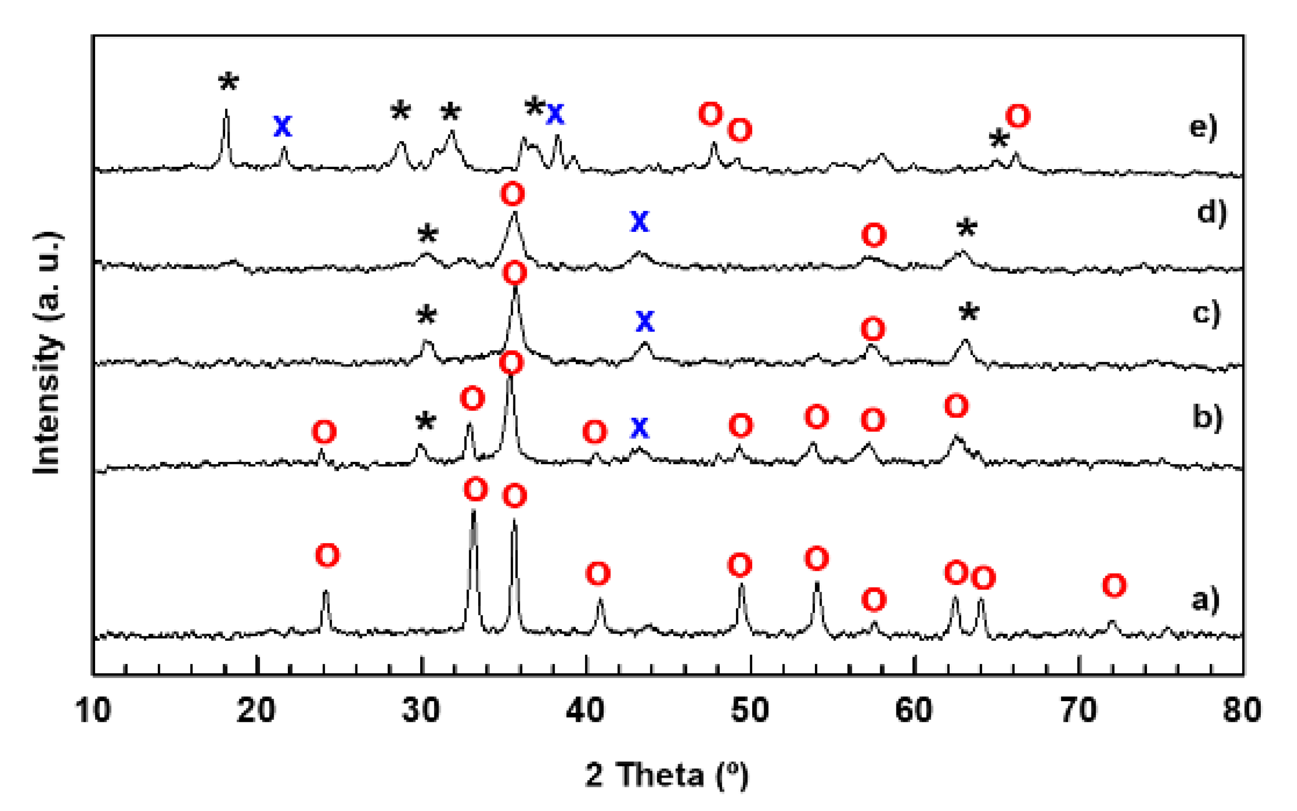
The possible crystallographic changes of the catalysts after its modification with Mn were investigated by X-ray diffraction. The XRD patterns of the calcined catalysts are shown in Figure 1. The Fe sample showed diffraction peaks located at 2θ values characteristic of the rhombohedral Fe2O3 phase (α-Fe2O3 phase, space group R-3c; JCPDS 00-033-0664). In addition, the Mn-promoted iron samples showed diffraction peaks at values characteristic of the tetragonal Mn3O4 (space group I41/amd, JCPDS 00-024-0734) and orthorhombic MnO (JCPDS 00-004-0326) crystals. The diffraction peaks corresponding to the manganese oxide phases were of low intensity, except in the sample with higher Mn content. The addition of manganese significantly changes the crystallinity of the samples, decreasing the intensity of the diffraction peaks corresponding to the Fe2O3 phase. The average crystallite size of this phase (Table 2), calculated by applying the Debye-Scherrer equation, follows the trend: Fe (23.6 nm) >> MnFe-0.50 (13.4 nm) > MnFe-0.05 (9.4) > MnFe-15 (8.2 nm) > MnFe-0.35 (5.5 nm). This result implies that the addition of Mn decreases the crystallinity of the Fe2O3 phase, which is associated with the formation of more complex structures. It should be noted that reflections of isolated Mn3O4 and MnO phases were also observed in the bimetallic MnFe catalysts, indicating that manganese was not incorporated into the Fe2O3 network. Interestingly, in the case of the preparation of bulk Fe2O3 by microemulsion method [19], the particle size of the Fe catalyst was much larger (38 vs. 23.6 nm), decreasing to 27 nm when manganese was added to this sample.

2.1.2. Textural Properties

The nitrogen adsorption-desorption isotherms of calcined Fe and MnFe-0.05 catalysts are compared in Figure 2A. As can be seen, both catalysts exhibit type II isotherms with an H3-type hysteresis loop, indicative non porous particles with the pore size distribution extending to the macropore range [34]. The beginning of capillary condensation in the pores occurs at high relative pressure (P/P0 = 0.8), with the pores are completely filled with liquid at about P/P0 = 0.99. As compared to MnFe-0.05, the capillary condensation for pure Fe occurs at higher relative pressure (P/P0 = 0.89).
As an example, the BJH desorption pore size distribution of Fe and MnFe-0.05 is shown in the inlet of Figure 2A. As can be seen, in contrast to the Mn-free Fe sample, MnFe-0.05 catalyst exhibits a broad pore distribution in the 15–65 nm region, which explains its large N2 isotherm hysteresis loop. The observed tensile strength effect (TSE) is an artefact indicating the cavitation-induced evaporation [35]. The textural properties of the calcined catalysts are compiled in Table 2. The surface area values of the Mn-containing catalysts are in the range of 82–211 m2·g−1. Textural parameters, such as specific surface area BET (SBET), total pore volume (Vp) and mean pore diameter (dpore), followed the same trend: MnFe-0.05 > MnFe-0.15 >> MnFe-0.35 > MnFe-0.50 > Fe. The largest increase in SBET was observed for sample with the lowest manganese content while surface areas and pore volumes tend to decrease with increasing Mn loading. This is in agreement with that observed for bimetallic MnFe catalysts prepared by the microemulsion method [19]. Considering the XRD results (Table 2), the increase in specific surface area is probably associated with the much smaller Fe2O3 crystallite size of the Mn-promoted iron catalysts with respect to unpromoted Fe sample (Table 2) [19].

2.1.3. UV-vis Diffuse Reflectance Spectroscopy (DRS UV-vis)

Figure 2B shows the DRS UV-vis electronic spectra of the MnFe catalysts. The spectra corresponding to the bare Fe catalyst show three main signals at about 285, 363 and 505 nm. Considering the study by Mallick and Dash [37], the absorption bands appeared at 285 and 363 nm are due to ligand-to-metal charge-transfer (LMCT) transitions (direct transitions) combined with the Fe3+ ligand field transitions phase. The absorption band at 285 nm is associated with the A1(6S) to 4T1(4 P) transition while the that at 363 nm is due to is due to the ligand-metal charge transfer transitions 6A1(6S) to 4E(4D) and 6A1(6S) to 4 T1(4D) [37]. The third absorption band observed around 505 nm is indicative of double excitation processes 6A1(6S)+6A1(6S) to 4T1(4G)+4T1(4G) associated with Fe2+ ions. All three absorption bands confirmed the presence of the α-Fe2O3 phase [37]. After the addition of manganese, new absorption bands appear at 239 and 638 nm which are characteristic of the electronic transitions of manganese oxides. The band at 239 nm is associated with an O−2 → Mn3+ charge transfer (manganese in tetrahedral coordination) [38], while the band at 638 nm is related to the Mn2+ species [38]. The intensity of the band corresponding to Mn2+ species was similar for the MnFe-0.15 and MnFe-0.35 samples, and lower for the samples with higher Mn loading (MnFe-0.50). Similarly, the intensity of the band related to the Mn3+ species gradually decreased with increasing manganese content. The electronic spectrum of the sample with the lowest Mn loading (MnFe-0.05) has a similar shape to that of the bare iron sample, suggesting that the Mn3+ species might overlap with the Fe3+ species. As expected, the MnFe-0.05 and MnFe-0.15 catalysts with lower Mn content show the most intense adsorption bands associated with Fe ions.

2.1.4. Temperature-Programmed Reduction (TPR)

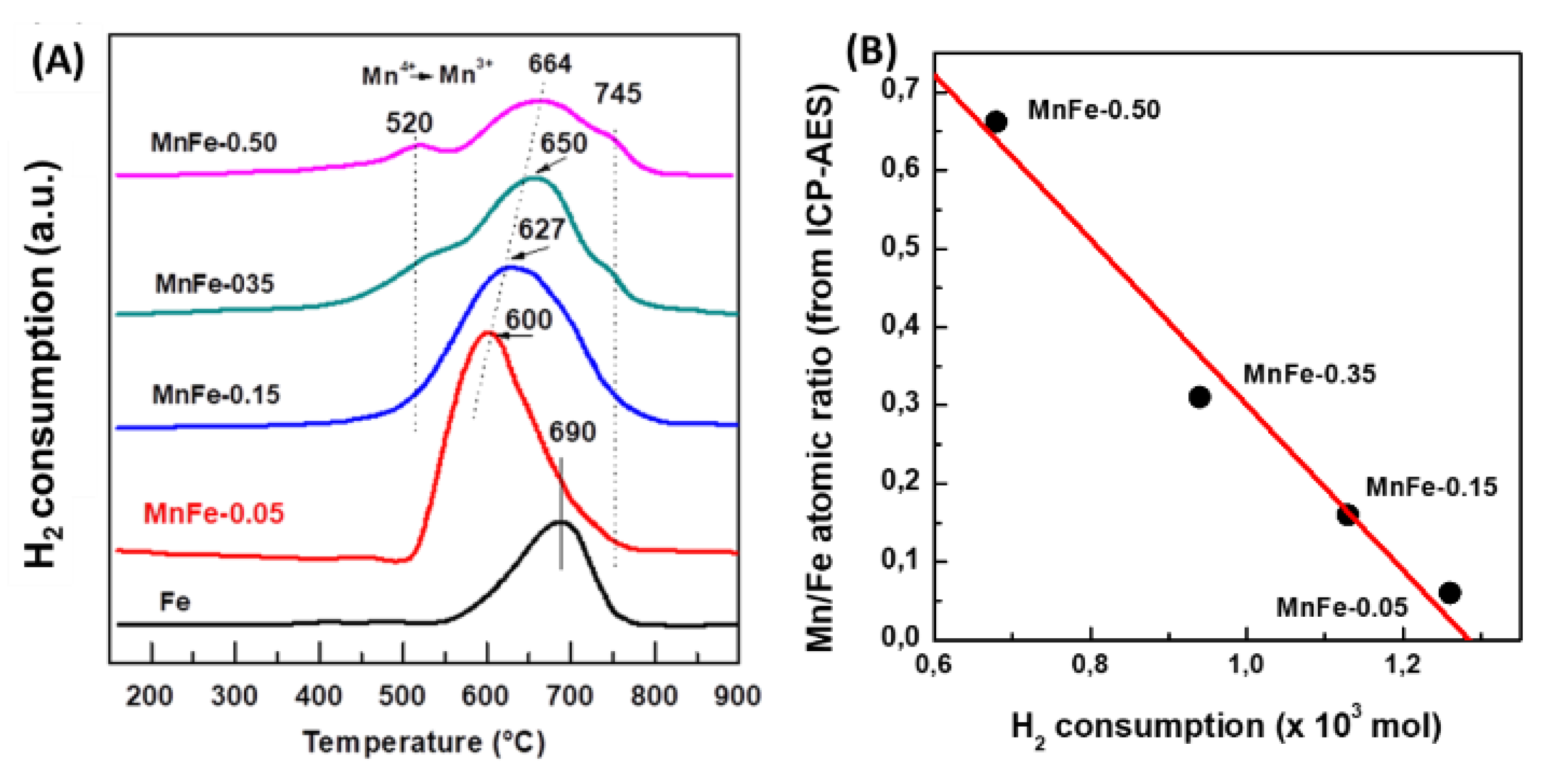
The reducibility of calcined Fe and MnFe catalysts was investigated by the temperature programmed reduction (TPR) technique. Figure 3A shows the reduction profiles of the bare Fe and all MnFe catalysts. The reduction profile corresponding to the bare Fe and Mn-0.05 catalysts shows a single asymmetric reduction peak (550-800 °C), with a maximum at approximately 690 °C associated with the H2 reduction process of Fe2O3 (hematite) → Fe3O4 (magnetite) → Fe0 [39]. It is noteworthy that, in the case of the MnFe-0.05 catalyst, the maximum of this peak shifts towards a lower temperature with respect to the bare Fe sample (from 690 to 600 °C), suggesting the enhancement of the reducibility of Fe2O3 after the incorporation of a small amount of MnO2 (6.1 wt.%) into the Fe sample. The position of the main reduction peak associated with the reduction of Fe2O3 follows the order: Fe (690 °C) > MnFe-0.50 (664 °C) > MnFe-0.35 (650 °C) > MnFe-0.15 (627 °C) > MnFe-0.05 (600 °C), indicating that the manganese loading caused an increase in the reducibility of the iron oxide species. Although the addition of a higher amount of Mn led to a gradual shift of the Fe2O3 peak towards a higher temperature region, the catalyst with higher Mn content still exhibits the peak maxima at a lower temperature than the bare Fe sample. Samples with higher Mn loading (MnFe-0.35 and MnFe-0.50) show two small reduction peaks at 520 °C and 745 °C due to the reduction of Mn3O4 to MnO [40]. Since thermodynamic predictions indicate that no subsequent reduction of MnO occurs, the peak at 745 ° may be associated with the reduction of Fe3+ to metallic iron [22]. Table 2 shows the theoretical H2 consumption required for the complete reduction of iron and manganese oxides (Table 2). The theoretical hydrogen consumption value was calculated assuming that the Fe2O3 phase is completely reduced to Fe0 and that manganese spinel oxide is reduced to manganese oxide only (Mn3O4 → MnO). Comparison of the experimental values with the theoretical values of H2 consumption suggests that the reduction of the Fe2O3 phase was not complete, in good agreement with what has been previously observed [16]. However, it is not ruled out that a minor fraction of metallic Fe may be formed.

2.2. Characterization of Fresh Reduced Catalysts

2.2.1. X-ray Photoelectron Spectroscopy (XPS)

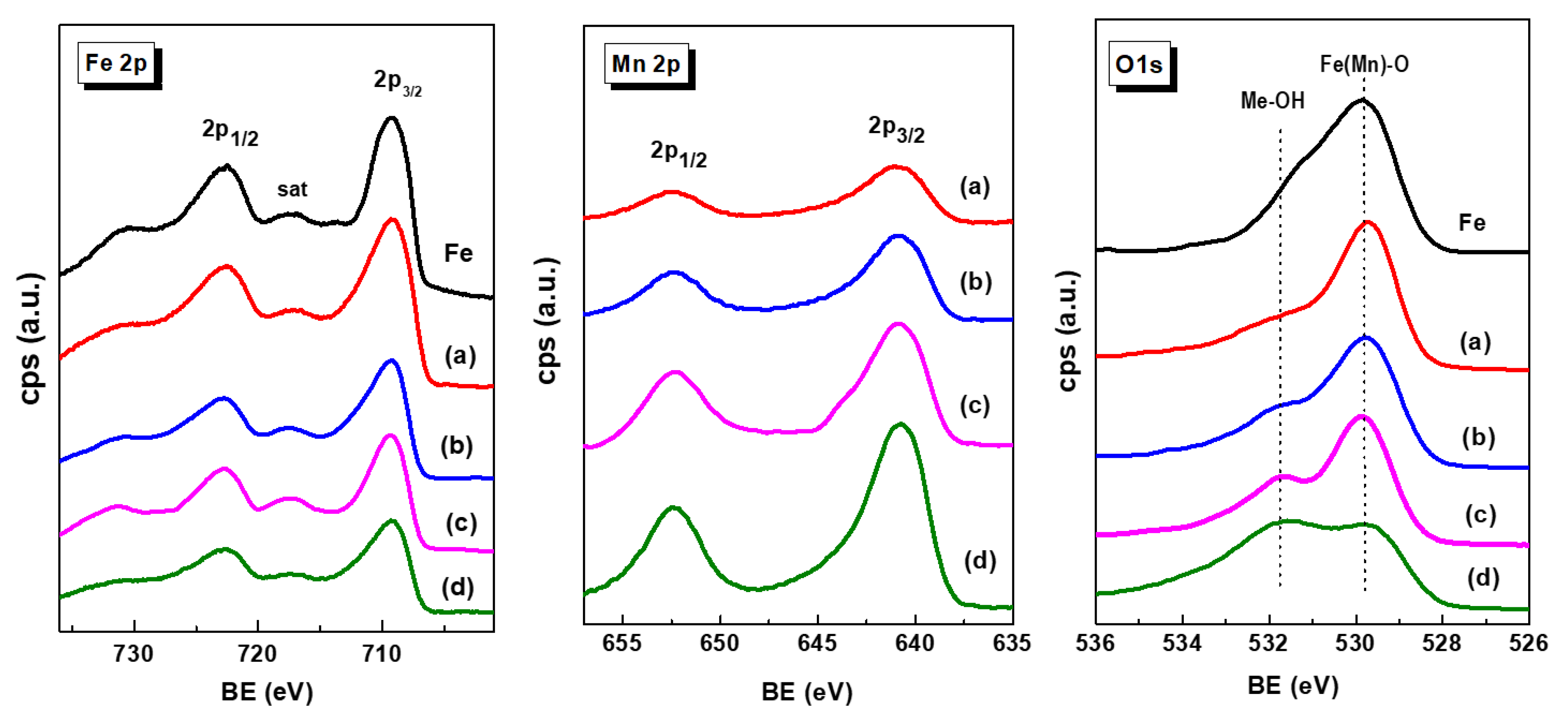
X-ray photoelectron spectroscopy was employed to investigate the nature of the iron and manganese species and their relative surface exposure after reduction at 450 °C for 1.5 h. Figure 4 show the Fe 2p, Mn 2p and O 1s core level spectra of the reduced Fe-based catalysts. The corresponding core-level binding energies and surface atomic ratios are summarized in Table 3. For all catalysts, the peak of the central C 1s level was at about 284.5 eV is characteristic of amorphous carbon [41]. No graphite, carbide or C-H carbon species were observed. The Fe 2p3/2 core level peak shows two binding energies at 709.2 and 710.6 eV typical of Fe2+ and Fe3+ ions, respectively, in an oxidized environment [42,43,44]. This is congruent with the satellite line located at approximately 717.3 eV, which is the footprint of Fe3+ ions [16].
Unlike the Fe 2p3/2 peak, the intensity of the Mn 2p3/2 peak increases with increasing Mn content due to the higher amount of manganese coating the iron species. The asymmetrical Mn 2p3/2 signal of each sample could be decomposed to two components at binding energies at 640.7 and 642.7 eV which are associated with the Mn3+ and Mn4+ species, respectively [45]. The asymmetric Mn 2p3/2 signal of each sample decomposed into two components indicate the presence of Mn3+ and Mn4+ ions, as deduced from the BE values at 640.7 and 642.7 eV, respectively. A satellite peak at 645.4 eV is due to the surface Mn3+ species [45]. As expected, the Mn/Fe atomic ratio values increase with increasing Mn content in the catalysts. The analysis of the O 1s core level indicated that all samples showed two oxygen species at 529.8 and 531.7 eV, corresponding to oxygen associated with metal oxide (Me) (Me-O-Me) and hydroxyl groups (Me-OH), respectively [42,43,44,45]. In the case of MnFe catalysts, the increase of the O/(Fe+Mn) ratio with Mn loading suggests an enhancement of the Mn-induced reducibility of Fe2O3 species, in agreement with TPR data.

2.2.2. FTIR of Adsorbed Pyridine (FTIR-Py)

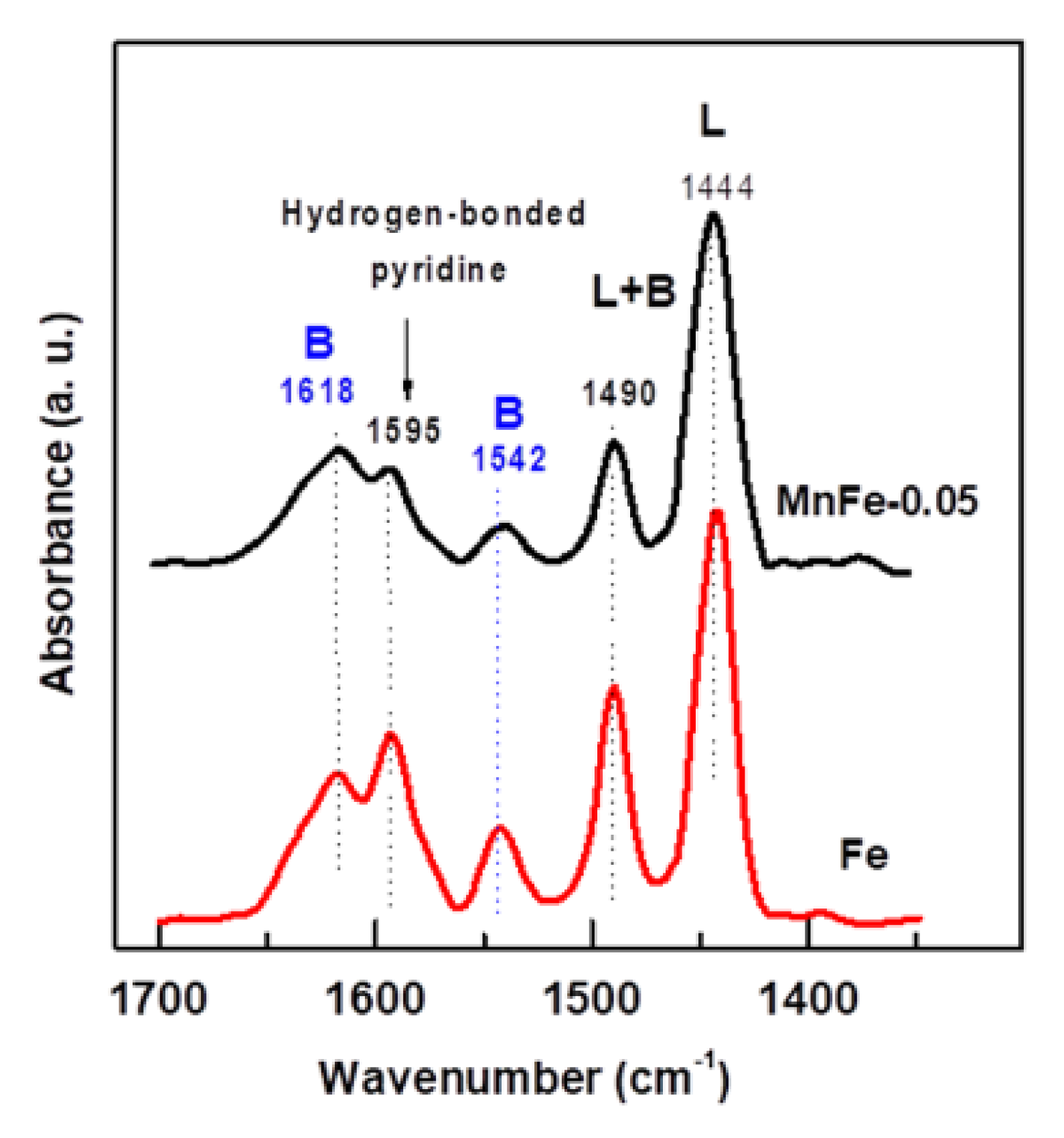
The change of the catalyst acidity after the incorporation of a small amount of manganese into the Fe catalyst was investigated by FTIR spectroscopy of adsorbed pyridine. As can be seen in Figure 5, in the 1400–1700 cm−1 spectral region, both Fe and MnFe-0.05 catalysts exhibit two strong bands assigned to Lewis site chemisorbed pyridine (1444 cm−1) and hydrogen bonded pyridine (1595 cm−1) [46,47]. A small band located at 1542 cm−1 and a high intensity band at 1618 cm−1 are assigned to pyridinium ion adsorbed on Brønsted sites, while a band observed at 1490 cm−1 is assigned to pyridine coordinated with both Lewis and Brønsted sites [47]. As expected, the bare Fe sample showed higher intensity of the absorption bands related to Lewis and Brønsted acid sites than the MnFe-0.05 catalyst. This was most evident for the 1542 cm−1 absorption band, suggesting that the MnFe-0.005 catalyst might have a lower amount of Brønsted acid sites than the bare Fe catalyst. In the case of bare Fe, the intensities of the absorption bands corresponding to Lewis and Brønsted acidities were 1.13 and 1.9 higher than in the MnFe-0.05 sample.

2.3. Catalytic Activity in the CO2 Hydrogenation

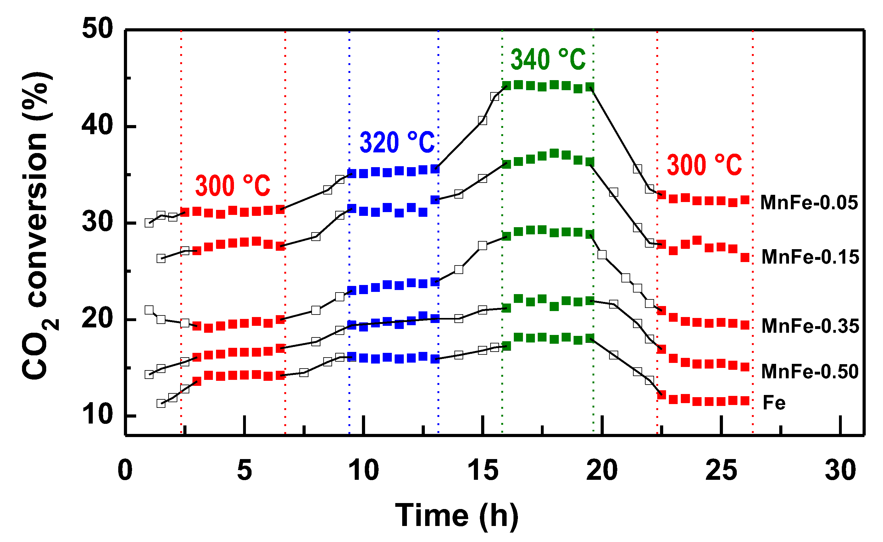
The activity of the reduced MnFe and bare Fe catalysts was determined in the CO2 hydrogenation reaction carried out in a flow reactor at three different temperatures (300, 320 and 340 °C), total pressure of 20 bar and H2/CO2 molar ratio=3. The reaction temperature was increased at 20 °C intervals during the run time until a temperature of 340 °C was reached. Subsequently, the temperature was lowered to 300 °C to determine whether catalyst deactivation occurred. Under the reaction conditions employed, all MnFe catalysts exhibit a pseudo-stationary state after approximately 4 h in stream.
Figure 6 shows the catalytic activity of the Fe and MnFe samples, expressed as CO2 conversion, as a function of reaction time and temperature. The bare Fe sample shows the lowest catalytic performance among all samples. For this sample, the CO2 conversion at 300 °C was 14.1%, reaching a maximum conversion of 17.8% at 340 °C. After reducing the reaction temperature to 300 °C, its CO2 conversion was 11.4%, which corresponds to 19.1% less than the initial conversion (14.1%). The catalytic activity of the MnFe samples increases respect the bare Fe counterpart, with the largest increases observed for the MnFe-0.05 catalyst. The CO2 conversion at 300 °C on the most active MnFe-0.05 catalyst was 30.9%, which is 2.2 times higher than that of the bare Fe catalyst. For MnFe-0.05 sample, the increase in temperature to 340 °C led to an increase in CO2 conversion to 44.1%, which is 2.3 times higher than that of the bare Fe sample. After lowering the reaction temperature to 300 °C, CO2 conversion over MnFe-0.05 catalyst was 32.5%, which indicates that the catalyst was reactivated after 26 h under reaction conditions. The catalytic performance of the MnFe catalysts, expressed as CO2 conversion at 340 °C, increases following the order: MnFe-0.05 (44.1%) > MnFe-0.15 (36.9%) > MnFe-0.35 (29.2%) > MnFe-0.50 (21.3%) > Fe (19.1%).
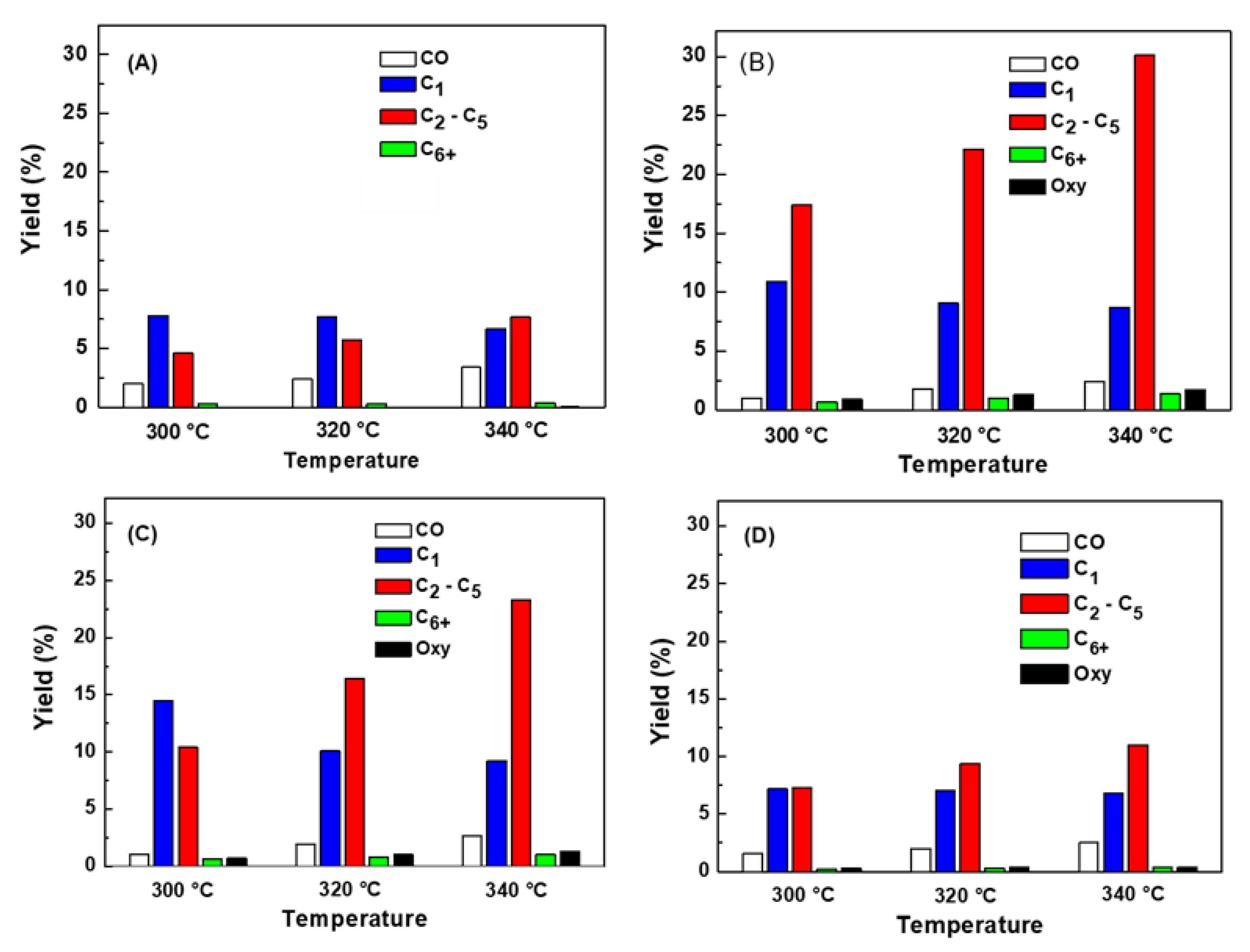
The effects of Mn loading and reaction temperature on product yields have been compared on bare Fe, MnFe-0.05, MnFe-0.15 and MnFe-0.50 catalysts under steady state conditions (Figure 7A–D). As expected, for all catalysts the product yields increased with increasing reaction temperature. Unlike methane, the yield toward the C2-C5 hydrocarbon fraction increased with increasing reaction temperature, so the addition of manganese favors the yield of these hydrocarbons. In this regard, MnFe-0.05 showed the highest yield towards the formation of the C2-C5 hydrocarbon fraction.
For bare Fe and MnFe catalysts, the yield of higher hydrocarbons (C6+) was very low, indicating that the chain growth process was limited to some extent. The chain growth process can be briefly explained as the insertion of an associatively adsorbed CO into the metal-alkyl bond; the termination of chain growth occurs when the product is desorbed from the catalyst surface [12]. Iron carbides are known to be an active phase in the transformation of CO through the FT reaction being responsible for chain growth [20]. Therefore, the small increase in C6+ formation observed in the Mn-promoted iron catalysts with respect to the non-promoted Fe catalyst could be due to their higher amount of forme iron carbides, as will be discussed below.
Figure 8A shows YCO/YHC ratio as a function of reaction temperature. As can be seen, hydrocarbon production during CO2 hydrogenation increases with increasing Mn content. The highest CO production with respect to hydrocarbon formation was observed for the bare Fe sample and its YCO/YHC ratio increases as a function of reaction temperature. Considering thermodynamics, this is expected because the increase in reaction temperature favors the RWGS reaction and CO formation. The addition of manganese suppressed CO formation; the lowest CO formation with respect to hydrocarbons was observed for sample MnFe-0.05. For the MnFe samples, the YCO/YHC ratio gradually increases with increasing reaction temperature, this being most notable for the samples with higher manganese content (Figure 8A).
Regarding the role of the Mn dopant and reaction temperature in olefin formation (Figure 8B), it was observed that the Mn loading and increasing the reaction temperature led to higher olefin formation in CO2 hydrogenation over MnFe catalysts with respect to the bare Fe catalyst. The observed differences in the olefin/paraffin ratio could be related to the formation of carbon species on the catalyst surface and the degree of carburization of the iron species, as discussed below. The higher formation of olefins respect paraffins (O/P ratio of 1.6) was archived for the catalyst with higher Mn loading (MnFe-0.50). Considering the decrease in catalyst acidity after Fe doping with Mn (Figure 6), the high O/P ratio of the MnFe-0.50 catalyst can be linked with its lower acidity. The decrease in catalyst acidity observed after Fe doping with Mn is in line with that study by Dokania et al [49], which modified the acidity of the zeolite ZSM-5 by incorporation of Ca. As a consequence of zeolite modification with Ca, Brønsted acidity was reduced and the formation of multiple Lewis acidic species leads to the enhancement of the light olefins production at the expense of longer chain hydrocarbons. The enhancement of the selectivity to light olefins was explained by authors as due to the creation of surface acetate species and suppression of oligomerization, which was favored by the reduction of the zeolite Brønsted acidity.
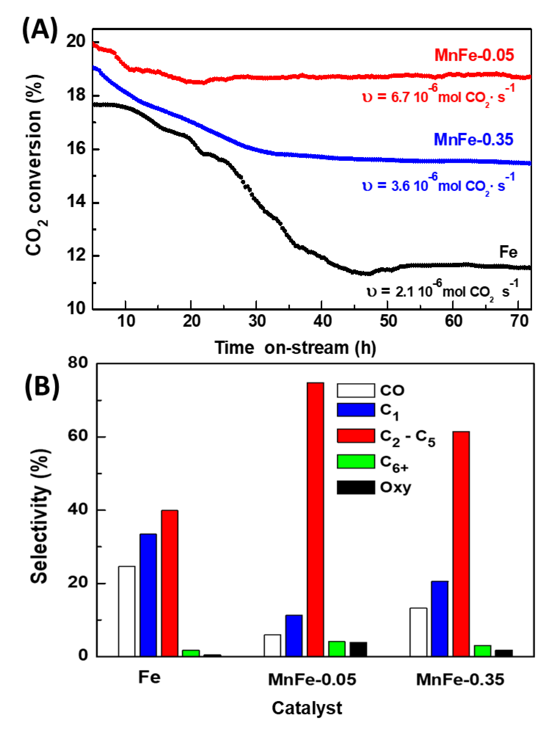
The stability of MnFe samples was evaluated at 340 °C for three representative samples: bare Fe, MnFe-0.05 and MnFe-0.35 (Figure 9A). To reduce the axial concentration gradients of CO2 and hydrogen, the conversion was kept at a low level (less than 20%). To achieve CO2 conversion around 20% it was necessary to vary the W/F ratio to 16, 7.7 and 12.2 gcat.·molCO2−1 for the bare Fe, MnFe-0.05 and MnFe-0.35 samples, respectively. Reaction rates values of the catalysts after 50 h time-on-stream, expressed as mol CO2 converted per second, are also included in Figure 9A. The highest reaction rate was observed for the MnFe-0.05 sample, with a value of 6.7 × 10⁻⁶ mol CO2·s−1, while the reaction rate for the rest of the samples follows the order: MnFe-0.05 > MnFe-0.35 > bare Fe. The MnFe-0.05 sample was 1.9 and 3 times more active than MnFe-0.35 and bare Fe samples, respectively. The MnFe-0.05 catalyst showed an initial CO2 conversion of 19.8% and reached stability (18.8%) after 20 h time-on-stream. Compared to MnFe-0.05, the MnFe-0.35 catalyst shows higher conversion loss, decreasing the initial conversion from 19.1%, to 15.6% after 36 h (loss of catalytic activity 18.2%). It is noteworthy that, unlike bare Fe, MnFe samples were stable for 72 h time-on-stream. Therefore, it is evident that manganese incorporation has a favorable effect on the activity and also in the stability of the samples, and this effect was more evident for the catalyst promoted with the lowest amount of Mn.
Figure 9B compare the selectivity of the Fe, MnFe-0.05 and MnFe-0.35 catalysts at 72 h on stream in reaction at 340 °C. As can be seen, the main products formed were C2-C5 hydrocarbons, followed by CH4 and CO. For both MnFe catalysts, the C6+ and oxygenated compounds were a little higher than on pure iron catalyst, but still they were the minor products indicating some difficulty in the production of high hydrocarbons. The bare Fe catalyst shows very high selectivity to CO (24.7%) and CH4 (35.5%) confirming CO formation via RWGS reaction. Promotion of the Fe catalyst with Mn largely decreased CO formation, but an increase of Mn content, from MnFe-0.05 to MnFe-0.35, led to twice higher CO production. Noticeably, the Fe promotion with Mn dramatically boosted the growth of carbon chains, leading to high formation of the C2-C5 hydrocarbons: MnFe-0.005 (74.8%) > MnFe-0.35 (61.7%) > bare Fe (37.3%). The selectivity of both MnFe catalysts toward C6+ hydrocarbons and oxygenated compounds were much lower than that of C2-C5 hydrocarbons but follows the same trend.
As compared to the Fe-based catalysts reported in literature, our best catalyst prepared with highest surface area exhibited better catalytic performance than the most of the catalysts reported in literature (Table 4). This can be, in part, explained as due to its better specific surface area allowing enhanced Mn dispersion on the surface of iron carbide. The most active MnFe-0.05 catalyst tested in this work was more selective towards light hydrocarbons (68 % vs 37%), but its O/P ratio in the reaction at 340 °C was much lower (2.7 vs 0.54). Under the reaction conditions employed (T = 350 °C, total pressure of 15 bar and H2/CO2 = 3), the bulk Fe2O3 catalyst (SBET of 5 m2·g−1) synthesized by Albretch et al. [20] showed somewhat lower CO2 conversion (40 %) and high selectivity to C5+ hydrocarbons (36%), which was explained as due to in situ transformation of Fe2O3 into active iron carbide(s) species.

2.4. Characterization of Spent Catalysts

2.4.1. Textural Properties

The textural properties of the catalysts after 72 h of CO2 hydrogenation at 340 °C are compiled in Table 5. As expected, the largest decrease of SBET was observed for the bare Fe catalyst (30.8%). In comparison, the surface area of the MnFe-0.05 and MnFe-0.35 samples decreased by only 8.5 and 16.7%, respectively, indicating that the modification of Fe catalyst with Mn greatly inhibits the loss of the catalyst specific surface area by coke deposition, as will be discussed below. Since the decrease of the mean pore diameter in MnFe used samples was much lower than that of SBET (9-12%) and the total pore volume remained constant for the Mn-doped iron catalysts, it seems that the coke deposition mainly occurs on the catalyst external surface and/or there was some increase of crystallite sizes.

2.4.2. Thermogravimetric Analysis (TGA-DTA)

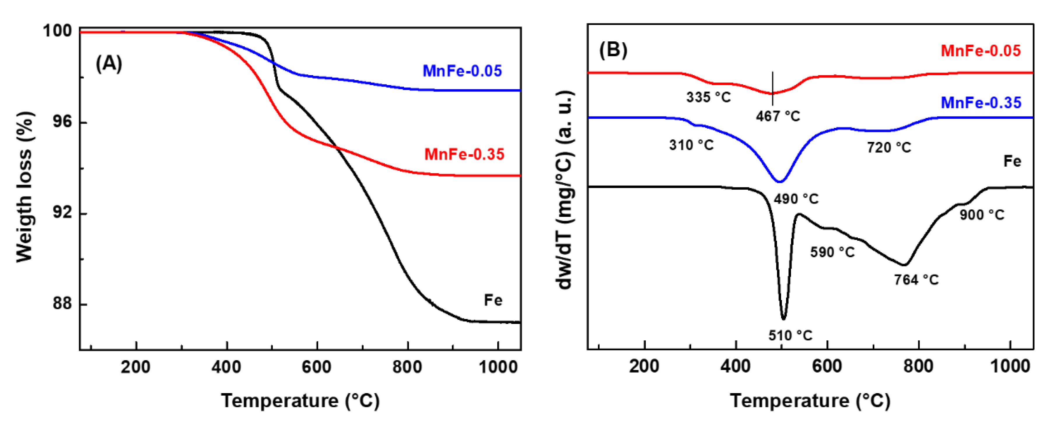
TGA/DTA analysis of the spent catalysts, performed in the range of 25 °C to 1100 °C, provided additional information on the type of carbon species present on the surface of the Fe, MnFe-0.05 and MnFe-0.35 catalysts after 72 h on stream in reaction at 340 °C. The weight loss and DTA profiles of the representative catalysts are shown in Figures 10A and 10B, respectively. The mass loss for the Mn-containing samples started at around 300 °C, whereas the weight loss for the bare Fe sample occurred at 490 °C and above. In good agreement with the literature [50], the unpromoted Fe catalyst exhibits much higher mass loss due to coke combustion (12.8%) than the MnFe-0.35 (6.3%) and MnFe-0.05 (2.6%) catalysts. The high coke formation on the surface of the Fe catalyst could explain its high decrease in SBET (38%) after 72 h on stream (Table 5).
Information on the type of coke formed was obtained by analyzing the DTA profiles shown in Figure 10(B). As expected, the bare Fe catalyst shows intense peaks at 510, 590, 764 and 900 °C attributed to coke combustion, being the coke more graphitic with increasing temperature [51,52]. It is noteworthy that the intensity of the DTA peaks decreased drastically with the addition of manganese. Furthermore, the DTA peak observed at higher temperature (900 °C) was not observed in the MnFe catalysts and an additional low intensity peak appeared at lower temperature (310 °C) in these samples. Interestingly, the Mn-containing catalysts shows the peak associated to coke combustion shifted to lower temperature: bare Fe (510 °C) > MnFe-0.35 (490 °C) > MnFe-0.05 (467 °C). These results indicate that the presence of manganese inhibits the formation of soft coke on the catalyst surface and decreases the degree of graphitization of carbon species (hard coke).

2.4.3. DRIFTS Analysis

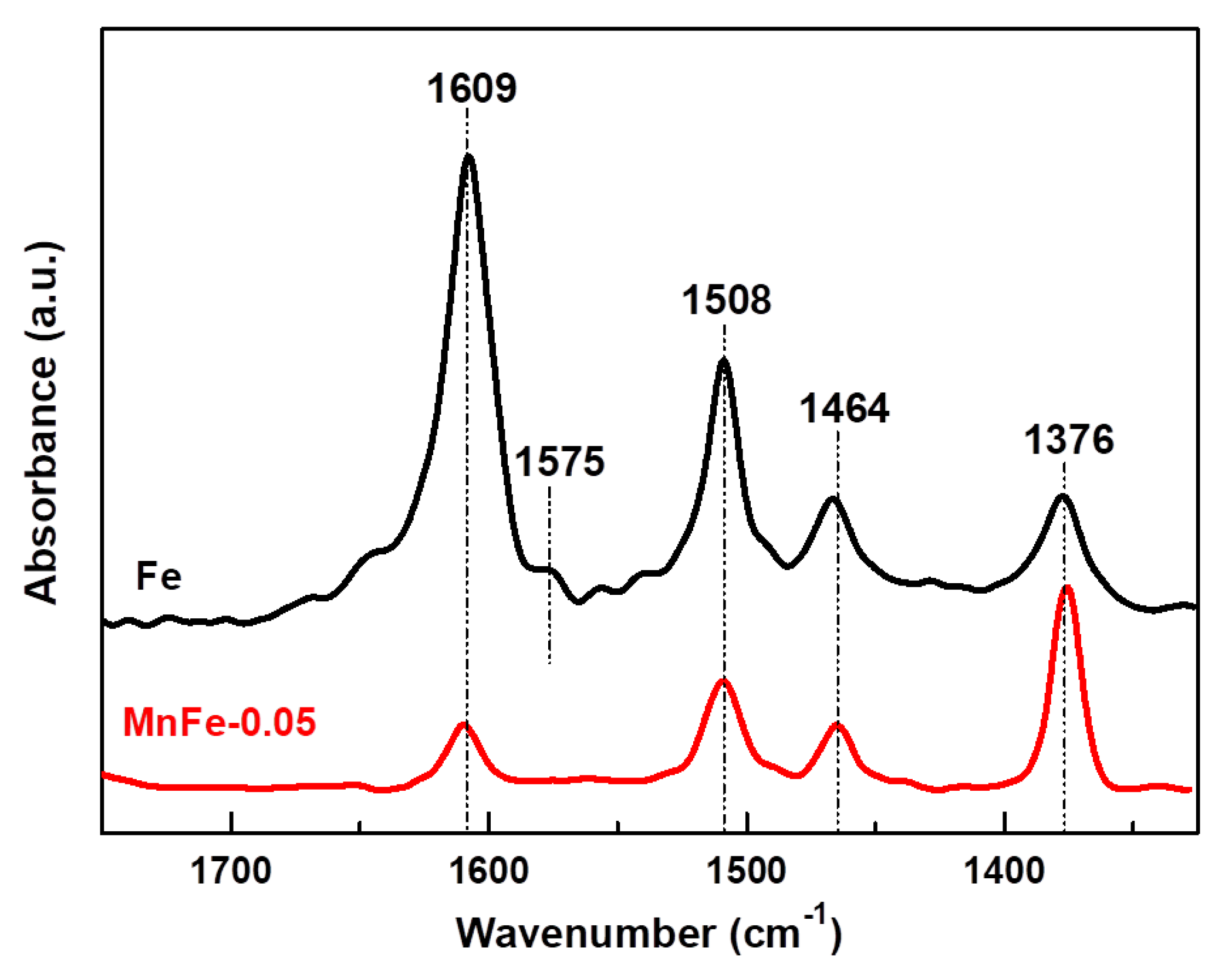
The presence of coke on the surface of the spent catalysts was also verified by DRIFT spectroscopy. Prior to analysis, the catalysts used were pretreated under Ar flow at 500 °C for 1 h to remove retained oligomers (soft coke). Figure 11 shows the 1700-1300 cm−1 region of the DRIFT spectra, where the vibrations of typical bending modes of aromatic and aliphatic carbons occur [53,54]. The DRIFT spectrum shows four signals at 1609, 1508, 1464 and 1376 cm−1. An additional band of lower intensity is observed for the bare Fe sample at 1575 cm−1. The 1609 cm−1 signal is assigned to the stretching vibration of C=C bonds of olefins or alkylbenzenes, the 1575 cm−1 signal corresponds to the C=C stretching vibration of polycyclic aromatic rings, the 1508 cm−1 signal is due to the C=C stretching vibration of alkylbenzene rings, which are associated with the presence of hard coke [53].
The 1464 and 1376 cm−1 bands, which are characteristic of soft coke, are associated with CH2 bending of C=C stretching vibration in aromatic rings and C-H bending modes of alkylbenzenes, respectively [53,54]. The bare Fe sample shows the highest intensity DRIFT signals, except the one observed at 1376 cm−1, compared to the MnFe-0.05 sample. These results indicate that in the bare Fe sample, hard coke on the surface is the main coke type. The MnFe-0.05 sample shows lower DRIFT intensities compared to the bare Fe samples. Furthermore, in this sample (MnFe-0.05), a significant fraction of the soft coke type was observed, compared to the hard coke type. These observations are in agreement with the TGA/DTA results. So, it could be assumed that the addition of manganese inhibited coke formation. It even decreases the growth on the surface of more complex coke species (hard coke). Coke formation is directly related to the catalytic stability of the samples in CO2 hydrogenation (Figure 9A).

2.4.4. Surface Analysis by XPS

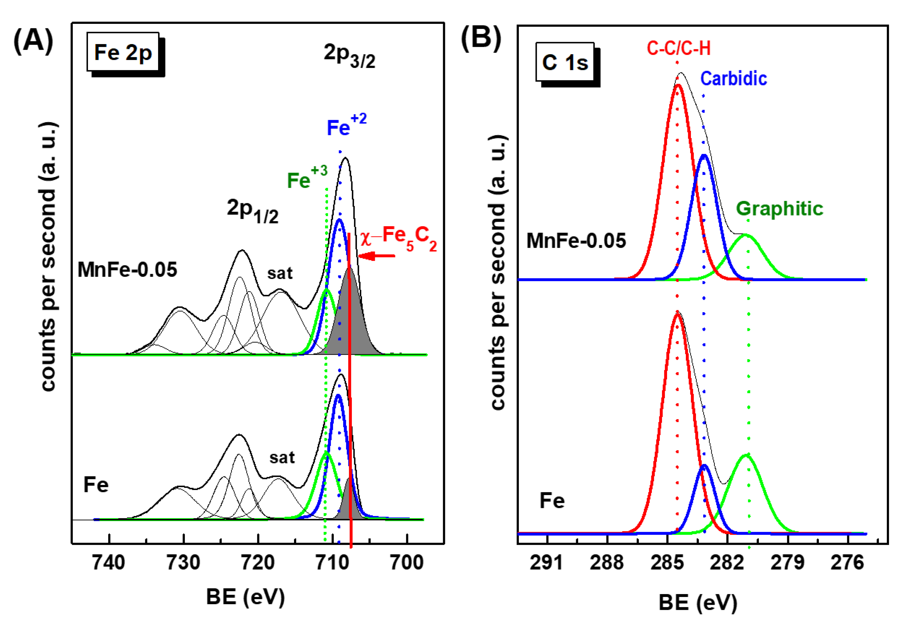
XPS characterization of the used Fe and MnFe-0.05 catalysts confirmed the positive effect of Mn promotion on the decrease of coke formation as well as the enhanced formation of the active phase χ-Fe5C2 under reaction conditions. Figure 12A shows the Fe 2p core level spectra of the used Fe and MnFe-0.05 catalysts, while Table 6 compiles their binding energies (eV) and the surface atomic ratios of the Fe, Mn and C species. For both Fe and MnFe-0.05 catalysts, the formation of the χ-Fe5C2 phase during 72 h on stream reaction was deduced from the Fe 2p3/2 peak at 707.7 eV. Comparison of the percentage of χ-Fe5C2 species formed indicates a three times higher amount of this phase on the surface of the MnFe-0.05 catalyst with respect to the bare Fe (31 and 11%, respectively). The others Fe 2p3/2 peaks with BE values at 709.2 and 710.6 eV correspond to the Fe3O4 and Fe2O3 phases, respectively [55]. For MnFe-0.05, the BEs values at 640.7 and 642.7 eV are associated with Mn3+ and Mn4+ species, respectively [45]. However, the recognition of the Mn4+ and Mn3+ species is difficult due to the small differences in their BE values [45].
More information on coke formation can be obtained by analyzing Figure 12B, which shows the C 1s core level spectra of both used catalysts. The C 1s peak shows three peaks with BE values at 281.1, 283.2 and 284.5 eV (Table 6). The main C 1s peak observed at 284.5 eV is characteristic of C-C/C=H groups (soft coke) with sp3 hybridized carbon (C-C-sp3) [56]. It is noteworthy that the signal of this peak was 1.2 times higher in the bare Fe sample compared to the MnFe-0.05 sample. The BE at 283.2 eV corresponds to carbidic carbon in the χ-Fe5C2 phase (C-Fe bonds) [55,57]. Finally, the C 1s peak at 281.1 eV can be attributed to C-C bonds belonging to graphitic carbon [55] The presence of these carbon species could be associated with the hard coke still remaining on the catalyst surface after surface cleaning with Ar at 500 °C for 1 h to remove hydrocarbons, permanent gases and adsorbed water.
The quantification of carbidic carbon, expressed as the C(carbide)/Fe atomic ratio (Table 6) indicate that two times higher amount of graphitic carbon was formed on the surface of bare Fe sample. Therefore, it can be concluded that the addition of manganese increases the carburization of iron species and inhibits the formation of hard coke on the surface, which are important factors for high yield and stability during CO2 hydrogenation.

2.5. Catalyst Structure-Activity Correlations

In this study, all catalysts were prepared by coprecipitation of manganese and iron nitrate salts, followed by drying under supercritical conditions and subsequent calcination. Due to the samples drying under supercritical conditions, the catalysts presented higher specific surface area (82-211 m2·g−1) than that described in the literature for Fe-based catalysts prepared without adding the structural promoter (20-67 m2·g−1) [31,32] or using structural directing agents [16]. It is noteworthy that the highest specific surface area (211 m2·g−1) was archived employing the lowest amount of Mn promoter (MnFe-0.05).
The Mn-promoted iron catalysts exhibited very different physicochemical properties with respect to the pure iron catalyst. Considering the factors that affect the activity and selectivity in the hydrogenation of CO2 on iron based catalysts [13,16,17,20] the better catalytic behavior of the MnFe.0.05 catalyst can be explained by considering the combined effects of its best textural properties, optimized acidity and largest amount of χ-Fe5C2 active phase. This is in agreement with that reported for Mn-promoted Na-CuFeO2 catalysts, which improved catalytic activity and selectivity towards lower chain olefins was attributed to the increased basicity of the catalyst and the easier formation of Hägg carbide (χ-Fe5C2) active sites due to the higher reducibility of the catalyst [33]. The kinetic study on the effect of Mn promotion confirmed the decrease in activation energy of direct CO2 hydrogenation [33].
The selectivity results (Figure 9B) suggest an indirect mechanism in the CO2 hydrogenation to C2-C5 products. Briefly, this mechanism can be described as the formation of CO on small crystals of iron oxide species, while iron carbides activate hydrocarbon formation via chemisorbed CO by reaction with hydrogen [58,59,60]. Among the iron carbide species, the Hägg carbide phase (χ- Fe5C2) is possibly the main phase for hydrocarbon formation via carbon chain growth from CO and H2 [61,62,63]. Although the presence of other catalytically active iron carbide phases cannot be excluded [12,64]. Considering combined XPS and TPR data, the drop in activity with increasing Mn content could be explained by the coverage of Fe2O3 particles by MnO/Mn3O4 species inhibiting the formation of χ-Fe5C2 and/or by the formation of non-active Fe3C carbides [12].
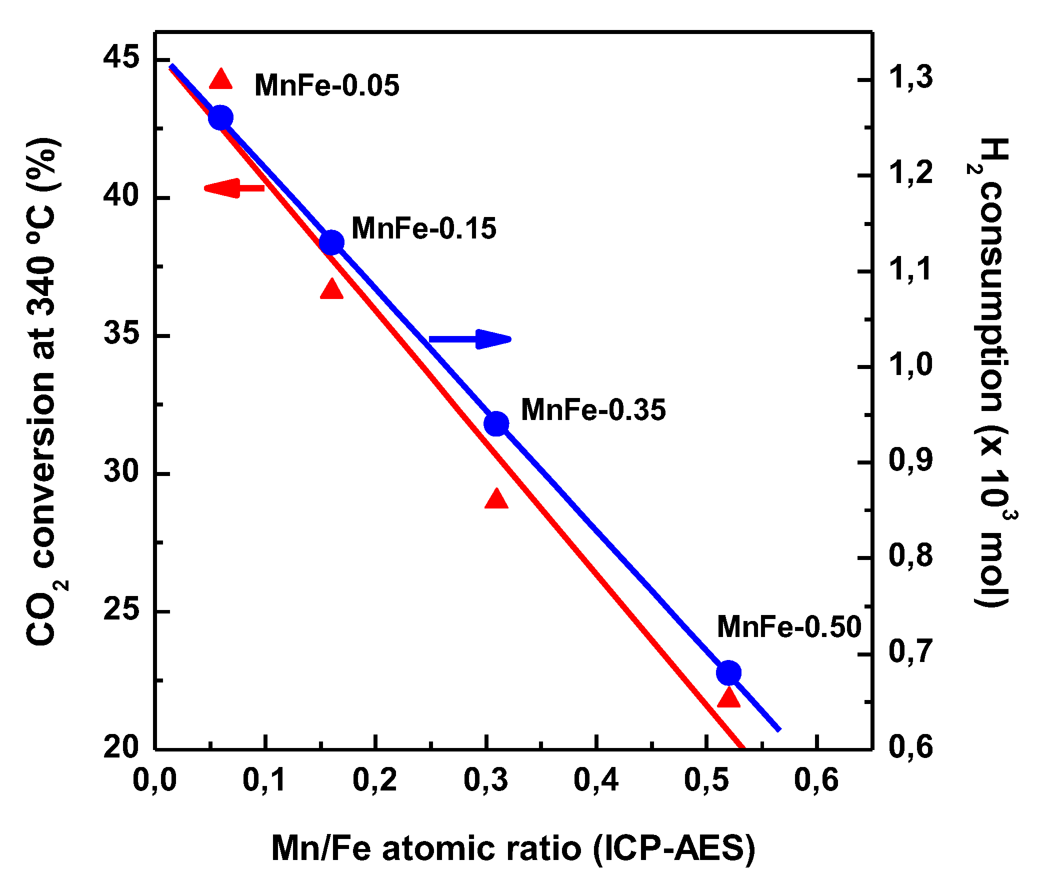
TPR results (Figure 3A) indicate that the formation of small crystals of Fe2O3 phase facilitates the reducibility of iron species. Interestingly, an increase in the Mn content in the Fe catalysts led to a simultaneous decrease in both H2 consumption during reduction of iron phases and CO2 conversion (Figure 13). This fact is indicative of a relationship between the CO2 conversion and the reducibility of Fe2O3 species. If we consider the presence of the Fe2+ species as an indicator of the reducibility of the iron species, the MnFe-0.05 and bare Fe samples showed the highest and lowest reducibility of Fe2+ species, respectively (Table 5). Therefore, the best catalytic behavior of MnFe-0.05 could be associated to the easier transformation of Fe2O3 to χ-Fe5C2 active phase needed for the FT synthesis [58]. Taking into account that the reduction of CO2 to CO occurs on the iron oxides and bare Fe catalyst contain the largest amount of both Fe2O3 and Fe3O4 (from XPS, Table 6), the bare Fe catalyst has better conditions for the CO formation via RWGS reaction than MnFe-0.05 catalyst, as it is confirmed by its largest YCO/YHC ratio (Figure 8A).
Since different factors influence catalyst deactivation (particle sintering, coke deposition, loss of active phases and specific surface area, etc.), it is not surprising that some researchers consider that carbonaceous deposits do not have a major influence on activity [60,61,62,63,64,65], while others claim that carbon deposition on iron-based catalysts suppresses their activity [65]. In addition, the study of Lee et al. showed that the catalyst deactivation is highly dependent on the position of the catalyst in the bed reactor: in the inlet part of the reactor the catalyst is deactivated due to phase transformation (χ-Fe5C3  Fe3C not active), while in the outlet part of the reactor side reactions lead to coke formation. Recently, it was suggested that the mayor factor responsible for catalyst deactivation in the CO2 hydrogenation over bulk iron catalyst might to be the irreversible oxidation of iron carbide to Fe3O4 [64]. The continuous Fe2O3 phase transition has been proposed: iron carbide formation (Fe2O3 → χFe5C2), deactivation (χ-Fe5C2 → Fe3O4) and regeneration (Fe3O4 → Fe5C2) [64]. Assuming this cycle, the stability of our most active MnFe-0.05 catalyst during 72 h on stream can be associated to the higher χ-Fe5C2 phase formation (as XPS data demonstrated) as a result of a more effective deactivation and regeneration cycle. In addition, the lower coke formation could also explain the higher activity and stability of the MnFe-0.05 catalyst with respect to the bare Fe catalyst considering that the presence of manganese inhibits the formation of soft coke and decreases the degree of graphitization of carbon species (hard coke) that can block surface active sites.
Finally, we conclude that it should be advantageous for the production of light olefins, if our best MnFe-0.05 catalyst operates at high temperature (340 °C) and will be additionally promoted by any alkaline promoter (preferentially K). This is because the alkali metal acts as an electronic and textural promoter improving the rate and selectivity towards large hydrocarbons and olefins [12].

3. Materials and Methods

3.1. Catalyst Preparation

Usupported Mn-Fe2O3 samples (MnFe) with different atomic Mn/Fe ratio (= 0.05, 0.15, 0.30 and 0.50) were prepared by the coprecipitation using manganese(II) nitrate (Aldrich, reagent, ≥98%) and hydrated iron(III) nitrate (Aldrich, reagent, ≥98%) as manganese and iron precursors, respectively. First, both precursors were dissolved separately in 1-butanol (Aldrich, reagent, ≥99%). Both solutions were then mixed, before 10 mL of a 10% solution of Triton™ X-100 (in H2O) was added, and subsequently precipitated while maintaining a pH of 9.5 using a 1 M solution of ammonium hydroxide (Aldrich, ACS reagent). The addition of an aqueous NH4OH solution to the mixed solutions of both precursors leads to the precipitation of Fe and Mn ions as oxyhydroxides. The solid obtained was first washed with deionized water, followed by three washes using a 50:50 mol mixture solution of 1-butanol and isopropyl alcohol (Aldrich, reagent, ≥ 99.7%). The obtained material was dried under supercritical conditions (240 °C and N2 pressure of 30 bar). Subsequently, the materials were dried for 24 h at room temperature, followed by drying at 75 °C for 40 h. Finally, the samples were calcined in a muffle with a heating ramp of 1 °C.min−1 at 500 °C for a period of 4 h. The dried precipitates were decomposed into hematite (Fe2O3) and MnO/Mn3O4 by calcination.

3.2. Catalyst Characterization

The elemental composition of the synthesized catalysts was determined by ICP-AES, Perkin Elmer Optima 3300DV. The textural properties of the calcined and used catalysts (after 72 h of CO2 hydrogenation at 340 °C) were determined by N2 adsorption-desorption isotherms recorded at -196 °C with a TriStar II 3020 Micromeritics equipment. Prior to N2 physisorption measurements, the calcined samples were degassed in vacuum at 120 °C for 16 h, while the catalysts used were pre-dried at 500 °C under ultra-high purity Ar flow (99.999%) for 1 h to remove hydrocarbons, permanent gases and physisorbed water from their surface, and then degassed under the same conditions as the calcined catalysts. The pore volume of the catalysts was measured at a relative pressure in the range of 0.995-0.998 while their specific surface area was determined by the Brunauer-Emmett-Teller (BET) method. The crystalline phases of the calcined catalysts were revealed by X-ray diffraction (Philip Equipment X'pert MPD) using a Cu Kα radiation source (γ=0.15418 nm), collected in the 2θ range of 10-75° with 0.02° step size and counting time of 1 s per spot. The redox properties of the calcined catalysts were studied by temperature-programmed reduction with H2 (TPR-H2) performed on a ChemBET Pulsar™ TPR/TPD apparatus. Prior to reduction, the catalysts (about 75 mg) were heated at a rate of 20 °C·min−1 to a temperature of 150 °C and held for 2 h under a flow of He to remove water and other contaminants, then reduced in flow gas containing 5% H2/N2 at a total flow rate of 100 mL min−1, and finally heated at a rate of 15 °C·min−1 to 800 °C. The electronic properties of the calcined and used catalysts were investigated by UV-vis diffuse reflectance spectroscopy (DRS) using a Varian Cary-5000 UV Vis spectrophotometer. Before analysis, the used samples were pre-treated with Ar for 1 h, then the spectra were collected. The nature of the acid sites of the synthesized catalysts was evaluated by FTIR spectroscopy of the adsorbed pyridine using a Nicolet 5700 FT-IR spectrometer. Prior to pyridine adsorption, the samples were reduced at 450 °C for 1.5 h with a H2/He gas mixture. The surface chemical properties of the fresh reduced and used catalysts was investigated by X-ray photoelectron spectroscopy recorded using a VG Escalab 200R spectrometer equipped with a hemispherical electron analyzer and a Mg Kα X-ray source (hν = 1253.6 eV). Samples were first placed in a stainless steel holder mounted on a sample rod in the pretreatment chamber of the spectrometer and then degassed at 150 °C for 1 hr before transfer to the analysis chamber. Charge effects were corrected by taking the binding energies (BE) of the C 1s peak of the adventitious carbon at 284.5 eV. Peak analyses were performed with software provided by VG and using the nonlinear least squares fitting program. The amount of coke deposited on the catalysts was determined using a TGA/SDTA851 thermogravimetric equipment (Mettler Toledo) by measuring the weight losses after oxidation of the coked catalysts. To remove hydrocarbons, permanent gases and adsorbed water on the surface, the samples were first dried at 500 °C under ultra-high purity Ar flux (99.999%) for 1 h, and then the samples were cooled to room temperature. Next, coke combustion was carried out by raising the sample temperature to a final temperature of 1150 °C at a rate of 5 °C min-1 in a 20% O2/N2 gas mixture.

3.3. Catalytic Activity

The catalysts were tested in a CO2 hydrogenation reaction carried out in a homemade packed bed continuous flow reactor operating in a downstream configuration. The catalyst (0.2 g) diluted with 1 g SiC was introduced into the reactor on glass fiber bed. Catalyst activation was performed in situ at atmospheric pressure by reduction with a 20 H2/80 He (v/v) gas mixture (flow =100 mL/min) using a heating ramp of 5 °C·min−1 up to 450 °C and following the reduction at this temperature for 1.5 h. The reactor was then cooled in the same gas mixture to the initial reaction temperature (300 °C) and pressurized to 20 bar. The H2/He gas mixture was then changed to a CO2/H2/N2=22/60/18 (vol. %) gas mixture (H2/CO2 molar ratio of 3; flow 20 mL·min-1) to achieve a space velocity W/FCO2 =16 gcat·h·molCO2−1. CO2 hydrogenation was measured at 300, 320 and 340 °C. For the evaluation of catalytic stability at long reaction times (72 h), W/FCO2 was varied between 7 and 16 gcat·h·molCO2−1 to obtain at 300 °C conversions < 20%. Analysis of the reaction products was performed on-line with gas chromatography using a special Agilent SP1 application for extended analysis of refinery gases (GC-SP1 7890-107).

4. Conclusions

In this study, we developed a simple and highly efficient method for the preparation of Mn-promoted high surface area bulk iron catalysts by co-precipitation of nitrate salts followed by drying under supercritical conditions and subsequent calcination. The effect of varying Mn loading on the catalyst physicochemical properties and activity in the hydrogenation reaction of CO2 to valuable products was investigated. The activity-structure correlation indicates that:
  • The best activity and selectivity results were obtained for the MnFe catalyst promoted with very low amount of Mn, which presents the best textural properties among the catalysts studied (SBET of 211 m2·g−1 and pore diameter of 15.8 nm).
  • Mn promotion of the bulk iron catalysts led to the main formation of C2-C4 hydrocarbons, while CO and methane formation was minimized. It was found a lineal correlation between yield of desired C2-C5 products and specific surface area of the catalysts.
  • The stability of the MnFe-0.05 catalyst in CO2 hydrogenation was greatly improved with respect to the bare Fe2O3 catalyst due to (i), the decrease of Bronsted acidity, and the consequent limitation of hard coke formation and (ii), the formation of the Hägg carbide phase during on stream reaction.
  • The catalyst synthesis method employed in this work offers a new solution for the fabrication of high area bulk iron catalysts for the CO2 hydrogenation reaction.

Author Contributions

Trino A. Zepeda designed the investigation, analyzed the data, and participated in writing the manuscript. Barbara Pawelec, Rufino M. Navarro Yerga, Juan C. Fierro and Sergio Fuentes analyzed the data, discussed the results, and participated in writing the manuscript. Sandra B. Aguirre, Alfredo Solis Garcia and Sergio Jimenez Lam conducted the experiments, analyzed the data and discussed the results. .

Funding

R.M.N.Y and B.P. gratefully acknowledge financial support from the Ministry of Science, Innovation and Universities under the research program PID2019-111219RB-100. T.A. Zepeda and S. Fuentes gratefully acknowledge financial support from CONACyT under the projects 117373 and IN112922.

Data Availability Statement

Data sharing is not applicable to this article.

Acknowledgments

The authors would like to thank Francisco Ruiz, David Dominguez, Eric Flores, J. Mendoza, Israel Gradilla, and Eloisa Aparicio for technical assistance.

Conflicts of Interest

The authors declare no conflict of interest.

References

  1. Jeffry, L.; Ong, M.Y.; Nomanbhay, S.; Mofijur, M.; Mubashir, M.; Show, P.L. Greenhouse gases utilization: A review. Fuel 2021, 301, 121017. [Google Scholar] [CrossRef]
  2. Li, N.; Mo, L.; Unluer, C. Emerging CO2 utilization technologies for construction materials: A review. J. CO2 Util. 2022, 65, 102237. [Google Scholar] [CrossRef]
  3. Min, J.; Yan, G.; Abed, A.M.; Elattar, S.; Khadimallah, M.A.; Jan, A.; Ali, H.E. The effect of carbon dioxide emissions on the building energy efficiency. Fuel 2022, 326, 124842. [Google Scholar] [CrossRef]
  4. Fu, L.; Ren, Z.; Si, W.; Ma, Q.; Huang, W.; Liao, K.; Huang, Z.; Wang, Y.; Li, J.; Xu, P. Research progress on CO2 capture and utilization technology. J. CO2 Util. 2022, 66, 102260. [Google Scholar] [CrossRef]
  5. Kim, C.; Yoo, C.-J.; Oh, H.-S.; Min, B.K.; Lee, U. Review of carbon dioxide utilization technologies and their potential for industrial application. J. CO2 Util. 2022, 65, 102235. [Google Scholar] [CrossRef]
  6. Chauvy, R.; Meunier, N.; Thomas, D.; De Weireld, G. Selecting emerging CO2 utilization products for short- to mid-term deployment. Appl. Energy 2019, 236, 662–680. [Google Scholar] [CrossRef]
  7. Li, J.; Wang, L.; Cao, Y.; Zhang, C.; He, P.; Li, H. Recent advances on the reduction of CO2 to important C2+ oxygenated chemicals and fuels. Chin. J. Chem. Eng. 2018, 26, 2266–2279. [Google Scholar] [CrossRef]
  8. Mota, N.; Ordoñez, E.M.; Pawelec, B.; Fierro, J.L.G.; Navarro, R.M. Direct synthesis of dimethyl ether from CO2: Recent advances in bifunctional/hybrid catalytic systems. Catalysts 2021, 11, 11040411. [Google Scholar] [CrossRef]
  9. Ronda-Lloret, M.; Rothenberg, G.; Raveendran Shiju, N. A Critical Look at Direct catalytic hydrogenation of carbon dioxide to olefins. Chem. Sus. Chem. 2019, 12, 3896–3914. [Google Scholar] [CrossRef]
  10. Numpilai, T.; Cheng, C.K.; Limtrakul, J.; Witoon, J.T. Recent advances in light olefins production from catalytic hydrogenation of carbon dioxide. Process Saf. Environ. Prot. 2021, 151, 401–427. [Google Scholar] [CrossRef]
  11. Pawelec, B.; Guil-López, R.; Mota, N.; Fierro, J.L.G.; Navarro Yerga, R.M. Catalysts for the conversion of CO2 to low molecular weight olefins - a review. Materials 2021, 14, 14226952. [Google Scholar] [CrossRef]
  12. Gonzalez, J.M.; Fierro, J.L.G. Fundamentals of Syngas Production and Fischer-Tropsch Synthesis. In “Biofuels from Fischer-Tropsch Synthesis” (Energy Science, Engineering and Technology; Ojeda, M., Rojas, S., Eds.; Nova Sci. Pub. Inc.: New York, 2010; ISBN 978-1-61668-366-5. [Google Scholar]
  13. Rodemerck, U.; Holeňa, M.; Wagner, E.; Smejkal, Q.; Barkschat, A.; Baerns, M. Catalyst development for CO2 hydrogenation to fuels. Chem. Cat. Chem. 2013, 5, 1948–1955. [Google Scholar] [CrossRef]
  14. Baea, J.-S.; Hong, S.Y.; Park, J.C.; Rhim, G.B.; Youn, M.H.; Jeong, H.; Kang, S.W.; Yang, J.-I.; Jung, H.; Chun, D.H. Eco-friendly prepared iron-based catalysts for Fischer-Tropsch synthesis. Appl. Catal. B: Environ. 2019, 244, 576–582. [Google Scholar] [CrossRef]
  15. Liu, J.; Song, Y.; Guo, X.; Song, C.; Guo, X. Recent advances in application of iron-based catalysts for CO hydrogenation to value-added hydrocarbons. Chinese J. Catal. 2022, 43, 731–754. [Google Scholar] [CrossRef]
  16. Al-Dossary, M.; Ismail, A.A.; Fierro, J.L.G.; Bouzid, H.; Al-Sayari, S.A. Effect of Mn loading onto MnFeO nanocomposites for the CO2 hydrogenation reaction. Appl. Catal. B: Environ. 2015, 165, 651–660. [Google Scholar] [CrossRef]
  17. Pérez-Alonso, F.J.; Ojeda, M.; Herranz, T.; Rojas, S.; González-Carballo, J.M.; Terreros, P.; Fierro, J.L.G. Carbon dioxide hydrogenation over Fe-Ce catalysts. Catal. Communications 2008, 9, 1945–1948. [Google Scholar] [CrossRef]
  18. Wu, X.; Qian, W.; Ma, H.; Zhang, H.; Liu, D.; Sun, Q.; Ying, W. Li-decorated Fe-Mn nanocatalyst for high-temperature Fischer–Tropsch synthesis of light olefins. Fuel 2019, 257, 116101. [Google Scholar] [CrossRef]
  19. Herranz, T.; Rojas, S.; Pérez-Alonso, F.J.; Ojeda, M.; Terreros, P.; Fierro, J.L.G. Hydrogenation of carbon oxides over promoted Fe-Mn catalysts prepared by the microemulsion methodology. Appl. Catal. A: Gen. 2006, 311, 66–75. [Google Scholar] [CrossRef]
  20. Albrecht, M.; Rodemerck, U.; Schneider, M.; Bröring, M.; Baabe, D.; Kondratenko, E.V. Unexpectedly efficient CO2 hydrogenation to higher hydrocarbons over non-doped Fe2O3. Appl. Catal. B: Environ. 2017, 204, 119–126. [Google Scholar] [CrossRef]
  21. Lohitharn, N.; Goodwin Jr., J. G.; Lotero, E. Fe-based Fischer–Tropsch synthesis catalysts containing carbide-forming transition metal promoters. J. Catal. 2008, 255, 104–113. [Google Scholar] [CrossRef]
  22. Leith, I.R.; Howden, M.G. Temperature-programmed reduction of mixed iron-manganese oxide catalysts in hydrogen and carbon monoxide. Appl. Catal. 1988, 37, 75–92. [Google Scholar] [CrossRef]
  23. Hutchings, G.J.; Boeyens, J.C.A. Effect of iron manganese oxide solid solutions on selectivity for lower hydrocarbons from carbon monoxide hydrogenation. J. Catal. 1986, 100, 507–511. [Google Scholar] [CrossRef]
  24. Millán Ordóñez, E.; Mota, N.; Guil-López, R.; Fierro, J.L.G.; Navarro Yerga, R.M. Direct synthesis of dimethyl ether on bifunctional catalysts based on Cu–ZnO(Al) and supported H3PW12O40: Effect of physical mixing on bifunctional interactions and activity. Ind. Eng. Chem. Res. 2021, 60, 18853–1886. [Google Scholar] [CrossRef]
  25. Wang, X.S.; Russell, C.K.; Tang, J.; Eddings, E.G.; Zhang, Y.; Fan, M. Effect of copper on highly effective Fe-Mn based catalysts during production of light olefins via Fischer-Tropsch process with low CO2 emission. Appl. Catal. B: Environ. 2020, 278, 119302. [Google Scholar] [CrossRef]
  26. Koo, H.M.; Ahn, C.-I.; Lee, D.H.; Roh, H.-S.; Shin, C.-H.; Kye, H.; Ba, J.W. Roles of Al2O3 promoter for an enhanced structural stability of ordered mesoporous Co3O4 catalyst during CO hydrogenation to hydrocarbons. Fuel 2018, 225, 460–471. [Google Scholar] [CrossRef]
  27. Liu, B.; Ouyang, B.; Zhang, Y.; Lv, K.; Li, Q.; Ding, Y.; Li, J. Effects of mesoporous structure and Pt promoter on the activity of Co-based catalysts in low-temperature CO2 hydrogenation for higher alcohol synthesis. J. Catal. 2018, 366, 91–97. [Google Scholar] [CrossRef]
  28. Cho, J.M.; Lee, S.R.; Sun, J.; Tsubaki, N.; Jang, E.J.; Bae, J.W. Highly Ordered Mesoporous Fe2O3–ZrO2 Bimetal Oxides for an Enhanced CO Hydrogenation Activity to Hydrocarbons with Their Structural Stability. ACS Catal. 2017, 7, 5955–5964. [Google Scholar] [CrossRef]
  29. Zhou, G.; Liu, H.; Xing, Y.; Xu, S.; Xie, H.; Xiong, K. CO2 hydrogenation to methane over mesoporous Co/SiO2 catalysts: Effect of structure. J. CO2 Util. 2018, 26, 221–229. [Google Scholar] [CrossRef]
  30. Liu, B.; Geng, S.; Zheng, J.; Jia, X.; Jiang, F.; Liu, X. Unraveling the new roles of Na and Mn promoter in CO2 hydrogenation over Fe2O3-based catalysts for enhanced selectivity to light α-olefins. Chem Cat. Chem. 2018, 10, 4718–4732. [Google Scholar]
  31. Visconti, C.G.; Martinelli, M.; Falbo, L.; Infantes-Molina, A.; Lietti, L.; Forzatti, P.; Iaquaniello, G.; Palo, E.; Picutti, B.; Brignoli, F. CO2 hydrogenation to lower olefins on a high surface area K-promoted bulk Fe-catalyst, Appl. Catal. B-Environ., 2017, 200, 530–542. [Google Scholar] [CrossRef]
  32. Tao, Z.; Yang, Y.; Zhang, C.; Li, T.; Ding, M.; Xiang, H.; Li, Y. Study of manganese promoter on a precipitated iron-based catalyst for Fischer-Tropsch synthesis. J. Nat. Gas Chem. 2007, 16, 278–285. [Google Scholar] [CrossRef]
  33. Zhao, H.; Guo, L.; Gao, W.; Chen, F.; Wu, X.; Wang, K.; He, Y.; Zhang, P.; Yang, G.; Tsubaki, N. Multi-promoters regulated iron catalyst with well-matching reverse water-gas shift and chain propagation for boosting CO2 hydrogenation. J. CO2 Util. 2021, 52, 101700. [Google Scholar] [CrossRef]
  34. Sadakane, M.; Horiuchi, T.; Kato, N.; Takahashi, C.; Ueda, W. Facile Preparation of Three-Dimensionally Ordered Macroporous Alumina, Iron Oxide, Chromium Oxide, Manganese Oxide, and Their Mixed-Metal Oxides with High Porosity. Chem. Mater. 2007, 19, 5779–5785. [Google Scholar] [CrossRef]
  35. Mercadal, J.J.; Mayoral, A.; Fierro, J.L.G.; García-Bordejé, E.; Mellán-Cabrera, I. Improved O2-assisted styrene synthesis by double-function purification of SWCNT catalyst. Chem. Eng. J. 2023, 455, 140723. [Google Scholar] [CrossRef]
  36. Zhang, Z.; Huang, G.; Tang, X.; Yin, H.; Kang, J.; Zhang, Q.; Wang, Ye. Zn and Na promoted Fe catalysts for sustainable production of high-valued olefins by CO2 hydrogenation. Fuel, 2022, 309, 122105. [Google Scholar] [CrossRef]
  37. Mallick, P.; Dash, B.N. X-ray Diffraction and UV-Visible Characterizations of α-Fe2O3 Nanoparticles Annealed at Different Temperature. J Nanosci. Nanotechnol. 2013, 3, 3–130. [Google Scholar] [CrossRef]
  38. Vazquez-Garrido, I.; Lopez-Benítez, A.; Guevara-Lara, A.; Berhault, G. Synthesis of NiMo catalysts supported on Mn-Al2O3 for obtaining green diesel from waste soybean oil. Catal. Today 2021, 365, 327–340. [Google Scholar] [CrossRef]
  39. De la Rosa-Priego, F.A.; Gutierrez-López, E.D.; Zepeda, T.A.; Acosta-Alejandro, M.; Venezia, A.M.; Fuentes-Moyado, S.; Pawelec, B.; Díaz de León, J.N. Enhanced CO2 Hydrogenation to C2+ hydrocarbons over mesoporous x%Fe2O3–Al2O3. Catal. Ind. Eng. Chem. Res. 2021, 60, 18660–18671. [Google Scholar] [CrossRef]
  40. Zhang, X.; Li, H.; Hou, F.; Yang, Y.; Dong, H.; Liu, N.; Wang, Y.; Cui, L. Synthesis of highly efficient Mn2O3 catalysts for CO oxidation derived from Mn-MIL-100. Appl. Surf. Sci. 2017, 411, 27–33. [Google Scholar] [CrossRef]
  41. Wang, J.; Chen, J.; Peng, L.; Zhang, H.; Jiang, Z.; Xiong, K.; Yang, Q.; Chen, J.; Yang, N. On the CuO-Mn2O3 oxide-pair in CuMnOx multi-oxide complexes: Structural and catalytic studies. Appl. Surf. Sci. 2022, 575, 151733. [Google Scholar] [CrossRef]
  42. Arrigo, R.; Schuster, M.E. On the high structural heterogeneity of Fe-impregnated graphitic-carbon catalysts from Fe nitrate precursor. Catalysts 2019, 9, 303. [Google Scholar] [CrossRef]
  43. Chen, C.; Ren, H.; Zhou, J.; Luo, Y.; Zhan, Y.; Au, C.; Lin, X.; Jiang, L. Cu/Fe3O4 catalyst for water gas shift reaction: Insight into the effect of Fe2+ and Fe3+ distribution in Fe3O4. Int. J. Hydrog. Energy 2020, 45, 8456–8465. [Google Scholar] [CrossRef]
  44. Hastuti, E.; Subhan, A.; Amonpattaratkit, P.; Zainuri, M.; Suasmoro, S. The effects of Fe-doping on MnO2: Phase transitions, defect structures and its influence on electrical properties. RSC Adv. 2021, 11, 7808–7823. [Google Scholar] [CrossRef] [PubMed]
  45. Ponce, S.; Peña, M.A.; Fierro, J.L.G. Surface properties and catalytic performance in methane combustion of Sr-substituted lanthanum manganites. Appl. Catal. B Environ. 2000, 24, 193–205. [Google Scholar] [CrossRef]
  46. Zhao, H.; Liu, J.-X.; Yang, C.; Yao, S.; Su, H.-Y.; Gao, Z.; Dong, M.; Wang, J.; Rykov, A.I.; Wang, J.; Hou, Y.; Li, W.-X.; Ma, D. Synthesis of iron-carbide nanoparticles: Identification of the active phase and mechanism of Fe-based Fischer-Tropsch synthesis. CCS Chem. 2020, 2, 20200055. [Google Scholar] [CrossRef]
  47. Zepeda, T.A.; Infantes-Molina, A.; Díaz de León, J.N.; Fuentes, S.; Alonso-Núñez, G.; Torres-Otañez, G.; Pawelec, B. Hydrodesulfurization enhancement of heavy and light S-hydrocarbons on NiMo/HMS catalysts modified with Al and P. Appl. Catal. A: Gen. 2014, 484, 105–121. [Google Scholar] [CrossRef]
  48. Yang, Q.; Skrypnik, A.; Matvienko, A.; Lund, H.; Holena, M.; Kondratenko, E.V. Revealing property-performance relationships for efficient CO2 hydrogenation to higher hydrocarbons over Fe-based catalysts: Statistical analysis of literature data and its experimental validation. Appl. Catal. B: Environ. 2021, 282, 119554. [Google Scholar] [CrossRef]
  49. Dokania, A.; Chowdhury, A.D.; Ramirez, A.; Telalovic, S.; Abou-Hamad, E.; Gevers,L. ; Ruiz-Martinez, J.; Gascon, J. Acidity modification of ZSM-5 for enhanced production of light olefins from CO2. J. Catal. 2020, 381, 347–354. [Google Scholar] [CrossRef]
  50. Zhang, Q. , Kang, J.; Wang, Ye. Development of Novel Catalysts for Fischer–Tropsch Synthesis: Tuning the Product Selectivity. Chem. Cat. Chem. 2010, 2, 1030–1058. [Google Scholar] [CrossRef]
  51. Kim, W.Y.; Lee, B.J.; Park, H.; Choi, Y.H.; Kim, J.H.; Lee, J.S. Ultrapermeable Nickel–Cobalt–Manganese/Alumina Inverse Opal as a Coke-Tolerant and Pressure-Drop-Free Catalyst for the Dry Reforming of Methane. Chem. Cat. Chem. 2018, 10, 2214–2218. [Google Scholar] [CrossRef]
  52. Lu, P.; Huang, Q.; Bourtsalas, A.C.; Chi, Y.; Yan, J. Effect of operating conditions on the coke formation and nickel catalyst performance during cracking of tar. Waste Biomass Valori. 2019, 10, 155–165. [Google Scholar] [CrossRef]
  53. Díaz, M.; Epelde, E.; Valecillos, J.; Izaddoust, S.; Aguayo, A.T.; Bilbao, J. Coke deactivation and regeneration of HZSM-5 zeolite catalysts in the oligomerization of 1-butene. Appl. Catal. B. Environ. 2021, 291, 120076. [Google Scholar] [CrossRef]
  54. Cepus, V.; Borth, M.; Seitz, M. IR Spectroscopic Characterization of Lignite as a Tool to Predict the Product Range of Catalytic Decomposition. Int. J. Clean Coal Energy 2016, 5, 13–22. [Google Scholar] [CrossRef]
  55. Jin, C.; Wang, B.; Zhou, Y.; Yang, F.; Guo, P.; Liu, Z.; Shen, W. Restructuring of the gold-carbide interface for low-temperature water-gas shift. Chem. Comm. 2022, 58, 7313–7316. [Google Scholar] [CrossRef] [PubMed]
  56. Nawaz, M.A.; M. Saif, M.; Li, M.; Song, G.; Zihao, W.; Chen, C.; Liu, D. Elucidating the synergistic fabrication of dual embedded (χ-Fe5C2 + θ-Fe3C) carbide nanocomposites in Na-FeCa@AC/HZSM-5 integrated catalyst for syngas conversion to aromatics. Fuel 2022, 324, 124390. [Google Scholar] [CrossRef]
  57. NIST X-ray Photoelectron spectroscopy database; http://srdata.nist.gov/xps/.
  58. Tu, W.; Sun, C.; Zhang, Z.; Liu, W.; Malhi, H.S.; Ma, W.; Zhu, M.; Han, Y.-F. Chemical and structural properties of Na decorated Fe5C2-ZnO catalysts during hydrogenation of CO2 to linear α-olefins. Appl. Catal. B. Environ. 2021, 298, 120567. [Google Scholar] [CrossRef]
  59. Otum, K.O.; Yao, Y.; Liu, X.; Hildebrandt, D. Synthesis, structure, and performance of carbide phases in Fischer-Tropsch synthesis: A critical review. Fuel 2021, 296, 120689. [Google Scholar] [CrossRef]
  60. Ding, J.; Huang, L.; Gong, W.B.; Fan, M.H.; Zhong, Q.; Russell, A.G.; Gu, H.; Zhang, H.J.; Zhang, Y.L.; Ye, R.P. CO2 hydrogenation to light olefins with high-performance Fe0.30Co0.15Zr0.45K0.10O1.63. J. Catal. 2019, 377, 224–232. [Google Scholar] [CrossRef]
  61. Xu, Y.; Zhai, P.; Deng, Y.; Xie, J.; Liu, X.; Wang, S.; Ma, D. Highly selective olefin production from CO2 hydrogenation on iron catalysts: A subtle synergy between manganese and sodium additives. Angew. Chem. Int. Ed. 2020, 59, 21736–21744. [Google Scholar] [CrossRef]
  62. Bukur, D.B.; Mukesh, D.; Patel, S.A. Promoter effects on precipitated iron catalysts for Fischer-Tropsch synthesis. Ind. Eng. Chem. Res. 1990, 29, 194–204. [Google Scholar] [CrossRef]
  63. Han, Y.; Fang, C.; Ji, X.; Wei, J.; Ge, Q.; Sun, J. Interfacing with carbonaceous potassium promoters boosts catalytic CO2 hydrogenation of iron. ACS Catal. 2020, 10, 12098–12108. [Google Scholar] [CrossRef]
  64. Zhang, Q.Y.; Cao, C.; Zhang, C.; Zhang, Z.; Liu, X.; Yang, Z.; Zhu, M.; Meng, B.; Xu, J.; Han, Y.-F. The study of structure-performance relationship of iron catalyst during a full life cycle for CO2 hydrogenation. J. Catal. 2019, 378, 51–62. [Google Scholar] [CrossRef]
  65. Zhao, H.; Liu, J.-X.; Yang, C.; Yao, S.; Su, H.-Y.; Gao, Z.; Dong, M.; Wang, J.; Rykov, A.I.; Wang, J.; Hou, Y.; Li, W.-X.; Ma, D. Synthesis of iron-carbide nanoparticles: Identification of the active phase and mechanism of Fe-based Fischer-Tropsch synthesis. CCS Chem. 2020, 2, 20200055. [Google Scholar] [CrossRef]
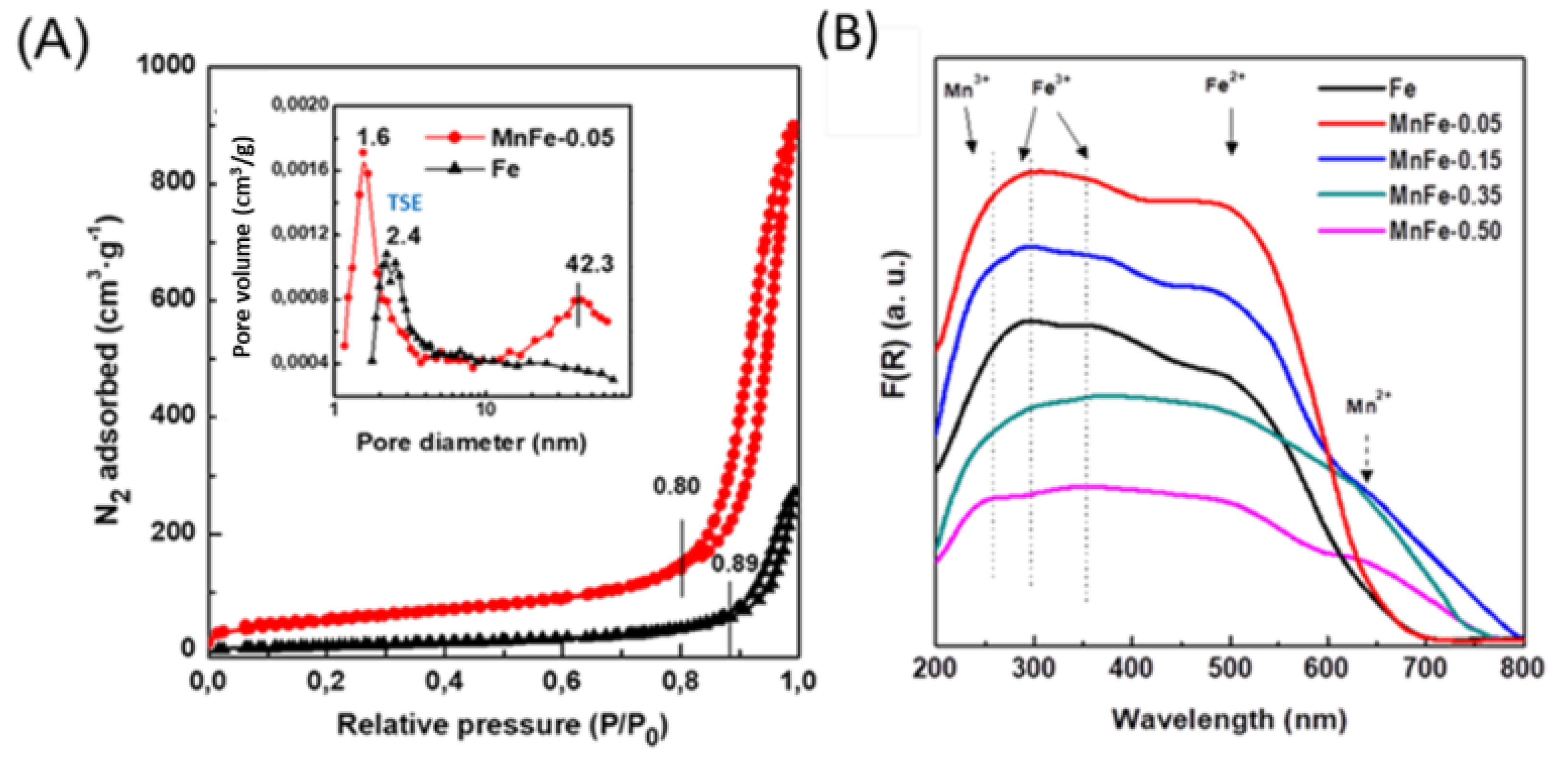
Figure 1. XRD patterns of calcined Fe and MnFe catalysts: (a), Fe; (b) MnFe-0.05; (c), MnFe-0.15; (d), MnFe-0.35; (e) MnFe-0.50; (*), Mn3O4 (JCPDS 00-020-0734); (o) Fe2O3 (JCPDS 00-033-0664); (x) MnO (JCPDS 00-004-0326).
Preprints 71846 g001
Figure 2. (A) N2 adsorption-desorption isotherms of calcined Fe and MnFe-0.05 calcined catalysts and their pore distribution shown in inlet; (B) DRS-UV-vis spectra of Fe and MnFe calcined catalysts.
Preprints 71846 g002
Figure 3. (A), TPR profiles of calcined Fe and MnFe catalysts. (B), Correlation between the Mn/Fe atomic ratio (from ICP-AES) and H2 consumption (from TPR).
Preprints 71846 g003
Figure 4. Fe 2p, Mn 2p and O 1s core level spectra of fresh reduced Fe and MnFe catalysts: (a), MnFe-0.05; (b), MnFe-0.15; (c), MnFe-0.35; (d), MnFe-0.050.
Preprints 71846 g004
Figure 5. FTIR spectra of pyridine adsorbed at 100 °C for pure Fe and MnFe-0.05 catalysts. The reduction of the samples was performed at 450 °C for 1.5 h with a heating ramp of 5 °C/min.
Preprints 71846 g005
Figure 6. Changes in CO2 conversion with temperature in the CO2 hydrogenation over reduced Fe and MnFe catalysts (P= 20 bar; H2/CO2 =3; W/FCO2= 16 gcat. h molCO2−1). This experimental condition is valid in agreement to the literature reports [48].
Preprints 71846 g006
Figure 7. Influence of temperature on the yield of products in CO2 hydrogenation on the most representative catalysts: (a), Fe; (b), MnFe-0.05; (c), MnFe-0.15 and (d), MnFe-0.50 (P= 20 bar; H2/CO2 =3; W/FCO2= 16 gcat. h molCO2−1).
Preprints 71846 g007
Figure 8. Evolution of YCO/YHC ratio (A) and olefin/paraffin ratio (B) with temperature. (P = 20 bar; H2/CO2 = 3; W/FCO2 = 16 gcat. h molCO2−1).
Preprints 71846 g008
Figure 9. (A) CO2 conversion vs. time on-stream and (B) selectivity after 72 h on stream. υ: reaction rate after 50 h TOS (T = 340 °C; P = 20 bar; H2/CO2 = 3; W/FCO2 = 7–16 gcat. h molCO2−1).
Preprints 71846 g009
Figure 10. TGA (A) and DTA (B) profiles of used Fe, MnFe-0.05 and MnFe-0.35 catalysts samples after 72 h on stream in CO2 hydrogenation at 340 °C.
Preprints 71846 g010
Figure 11. DRIFT spectra of used Fe and MnFe-0.05 catalysts after 72 h on stream CO2 hydrogenation.
Preprints 71846 g011
Figure 12. Fe 2p (A) and C 1s (B) core-level spectra of used Fe and MnFe-0.05 catalysts after 72 h on stream.
Preprints 71846 g012
Figure 13. Influence of Mn loading on the CO2 conversion at 340 °C and H2 consumption during reduction of calcined MnFe catalysts (from TPR).
Preprints 71846 g013
Table 1. Labelling and chemical composition of calcined Fe and MnFe catalysts .
Labelling Theoretical
Mn/Fe Atomic
Experimental (ICP-AES)
Mn/Fe Ratioa MnO2 (wt.%)a Fe2O3 (wt.%)a
Fe - - - 100
MnFe-0.05 0.05 0.06 6.1 93.9
MnFe-0.15 0.15 0.16 14.8 85.2
MnFe-0.35 0.30 0.31 25.2 74.8
MnFe-0.50 0.50 0.52 36.1 63.9
Table 2. Textural propertiesa, crystallite sizeb and H2 consumption during TPR measumerentsc for calcined Fe and MnFe catalysts.
Catalysts SBET
(m2/g)
Vp
(cm3/g)
dpore
(nm)
Fe2O3
Crystallite Size
(nm)
H2 Consumptionc (mmol·gcat−1)
Theoretical Experimental
Fe 65 0.4 22.5 23.6 1.17 0.50
MnFe-0.05 211 1.3 15.8 9.4 1.54 1.26
MnFe-0.15 152 1.1 15.2 8.2 1.50 1.13
MnFe-0.35 90 0.7 13.9 5.5 1.46 0.94
MnFe-0.50 82 0.6 14.8 13.4 1.41 0.68
a From N2 adsorption-desorption data at −196 °C. b From XRD. c The experimental hydrogen consumption values were quantified up to the maximum reduction temperature of the TPR experiments.
Table 3. Binding energies (eV) core levels and surface Mn/Fe atomic ratio of the freshly reduceda,b Mn-containing Fe-based catalysts.
Catalysts Fe 2p3/2 Mn 2p3/2 O 1s C 1s Mn/Fe at O/(Fe+Mn) at
Fe 709.2 (40%)
710.6 (60%)
- 529.7 (75%)
531.6 (25%)
284.5 - 2.28
MnFe-0.05 709.3 (61%)
710.6 (39%)
640.6 (57%)
642.7 (43%)
529.8 (71%)
531.7 (29%)
284.5 0.056 1.81
MnFe-0.15 709.1 (55%)
710.6 (45%)
640.7 (60%)
642.7 (40%)
529.8 (65%)
531.8 (35%)
284.5 0.196 1.96
MnFe-0.35 709.1 (51%)
710.6 (49%)
640.8 (63%)
642.7 (37%)
529.8 (58%)
531.7 (42%)
284.5 0.405 2.08
MnFe-0.50 709.2 (45%)
710.6 (55%)
640.7 (65%)
642.7 (35%)
529.8 (43%)
531.7 (57%)
284.5 0.662 2.23
a The reduction of the samples was carried out at 450 °C at a flow rate of 100 mL/min (H2 20% v/v; balance He), during 1.5 h with a heating ramp of a 5 °C/min. b The percentages of each species are shown in parenthesis.
Table 4. Comparison of the best catalyst of this work with previously reported Mn-promoted iron catalysts in terms of CO2 conversion, CO selectivity and yield of olefins in direct CO2 hydrogenation do light olefins.
Catalyst T
(°C)
P
(MPa)
CO2
conv. (%)
CO
Selectivity (%)
Yielda
C2-C4 (%)
Ref.
MnFe-0.05 340 2 44.1 68.0 30.0 This work
FeMnNa 340 2 35.0 18.1 11.1 34
10Mn-Na/Fe 320 3 37.7 12.9 12.9 35
2.5%Mn-NaCuFeO2 320 2 36.6 34.0 13.1 36
5Mn-Na/Fe 320 3 38.6 11.7 11.7 37
10Mn-Fe3O4 (microspheres) 350 2 44.7 9.4 21.6 38
0.09Mn/Fe3O4-NaAc 320 0.5 27.6 24.7 9.3 30
5NaFe 320 3 38.4 9.1 31.9 37
Fe-Mn-K 300 1 38.2 5.6 8.7 39
aYield(%) = Selectivity toward C2-C4 (%) × CO2 conversion.
Table 5. Textural propertiesa of spent catalystsb.
Catalysts SBET
(m2/g)
SBET lossc (%) Vpore (cm3/g) Vpore lossc (%) dp (nm)
Fe 45 30.8 0.3 25 19.3
MnFe-0.05 193 8.5 1.3 0 14.8
MnFe-0.35 75 16.7 0.7 0 12.4
a SBET: specific BET surface area; Vpore: total pore volume; dpore: mean pore diameter. Before analysis, the spent catalysts were degassed at 500 °C for 1.5 h. b After 72 h on stream; mcat = 0.2 g; T = 340 °C; P = 20 bar; H2/CO2 = 3; H2/CO2/N2 = 60/23/8. c Loss of SBET and Vpore values with respect to the calcined catalyst.
Table 6. Binding energies (eV) core levels and surface atomic ratios of used Fe and MnFe-0.05 catalysts after 72 h of CO2 hydrogenation. The percentage of each species is shown in the parentheses.
Catalyst Mn 2p3/2 Fe 2p3/2 C 1s Species C(Carbide)/Fe at
Fe -
707.7 (11%) 283.2 (13%) χ-Fe5C2 0.19
709.2 (54%) 284.5 (61%) Fe2+; C-C/C/C-H -
710.6 (35%) 281.1 (26%) Fe3+; graphitic C
MnFe-0.05 639.0(10%) 707.7 (31%) 283.2 (32%) χ-Fe5C2 0.38
640.7 (47%) 709.2 (51%) 284.5 (55%) Fe2+; C-C/C/C-H -
642.7 (43%) 710.6 (18%) 281.1 (13%) Fe3+; graphitic C
Disclaimer/Publisher’s Note: The statements, opinions and data contained in all publications are solely those of the individual author(s) and contributor(s) and not of MDPI and/or the editor(s). MDPI and/or the editor(s) disclaim responsibility for any injury to people or property resulting from any ideas, methods, instructions or products referred to in the content.
Copyright: This open access article is published under a Creative Commons CC BY 4.0 license, which permit the free download, distribution, and reuse, provided that the author and preprint are cited in any reuse.
Prerpints.org logo

Preprints.org is a free preprint server supported by MDPI in Basel, Switzerland.

Subscribe

© 2024 MDPI (Basel, Switzerland) unless otherwise stated