Preprint
Case Report

This version is not peer-reviewed.

Outcomes Of 3D-Guided Midpalatal Piezocorticotomy Combined with MARPE Expansion in Adults

Submitted:

06 September 2025

Posted:

08 September 2025

You are already at the latest version

Abstract

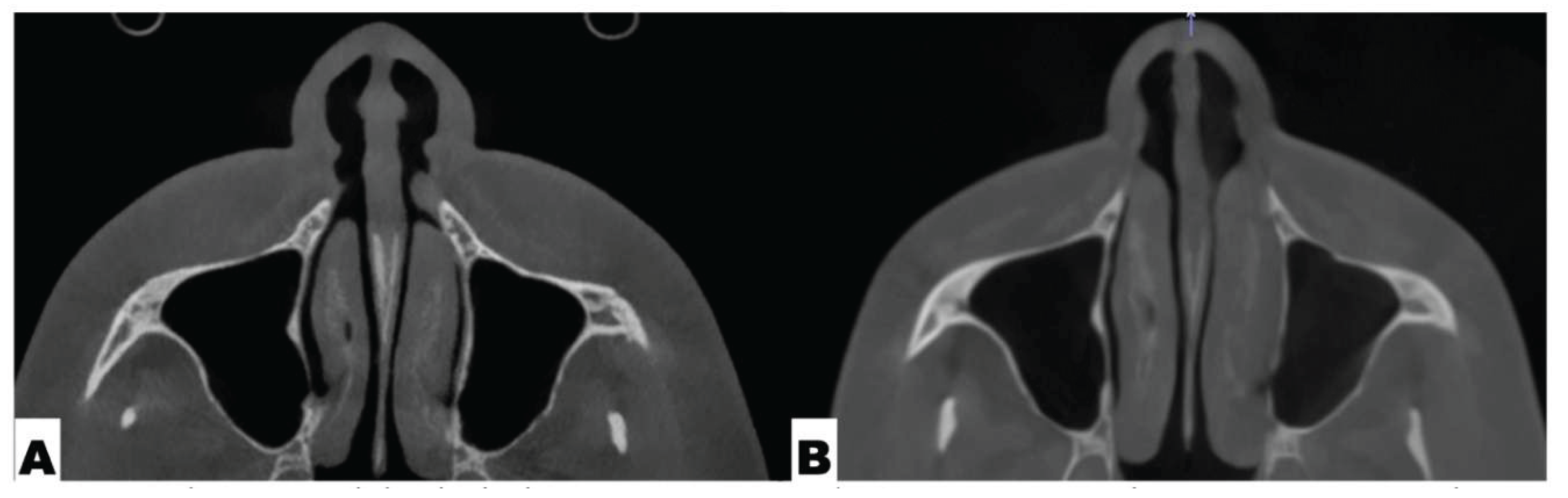
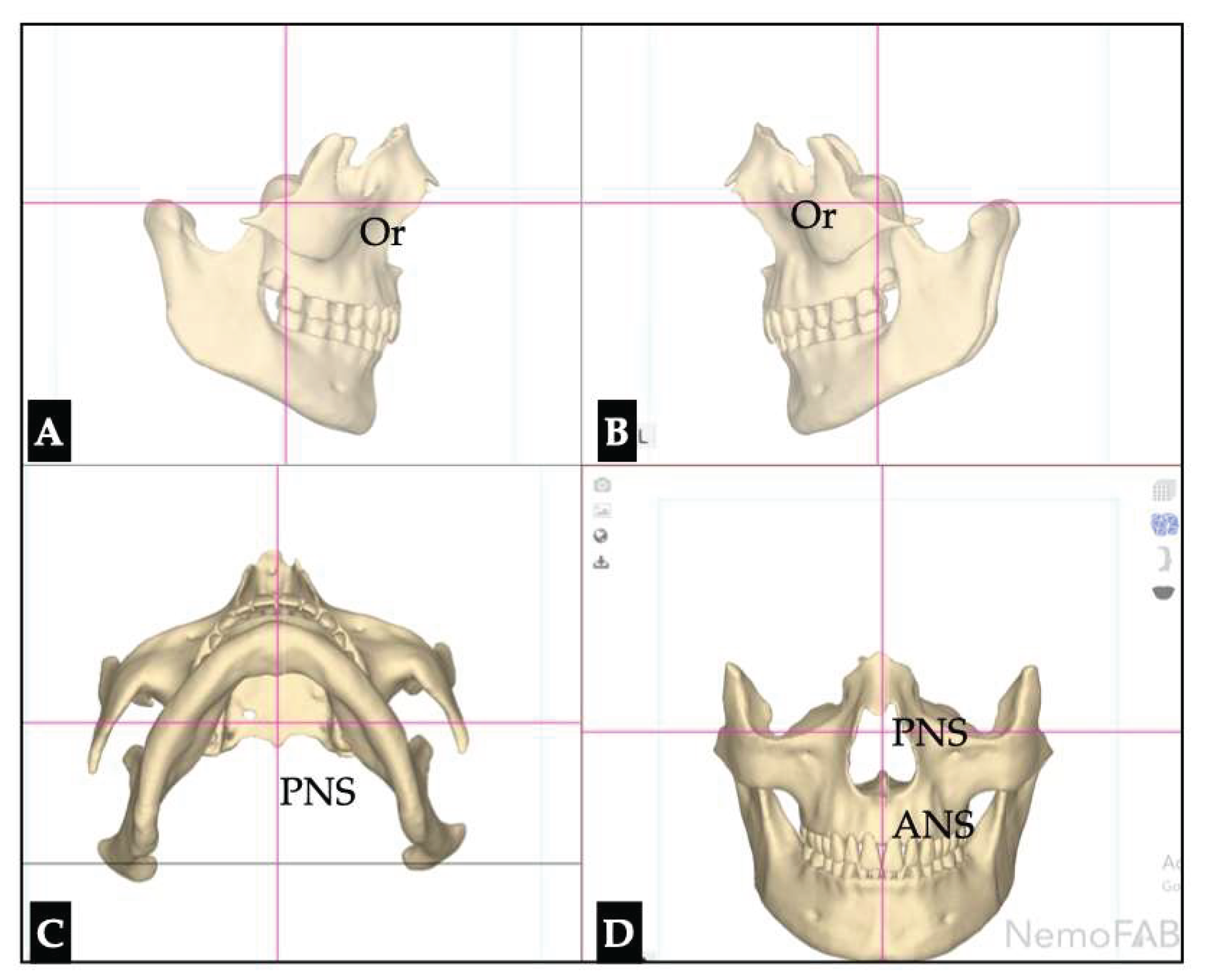
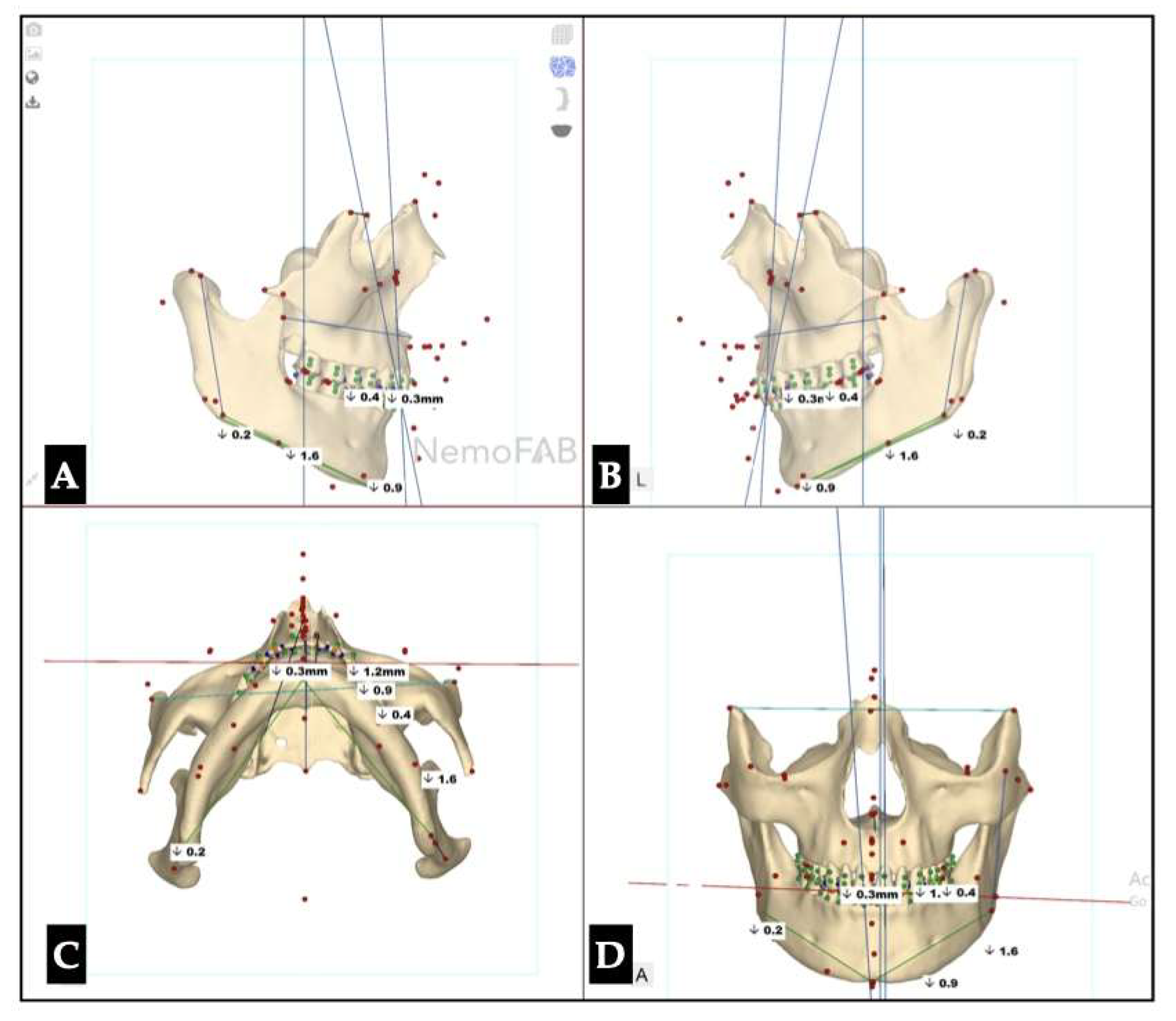
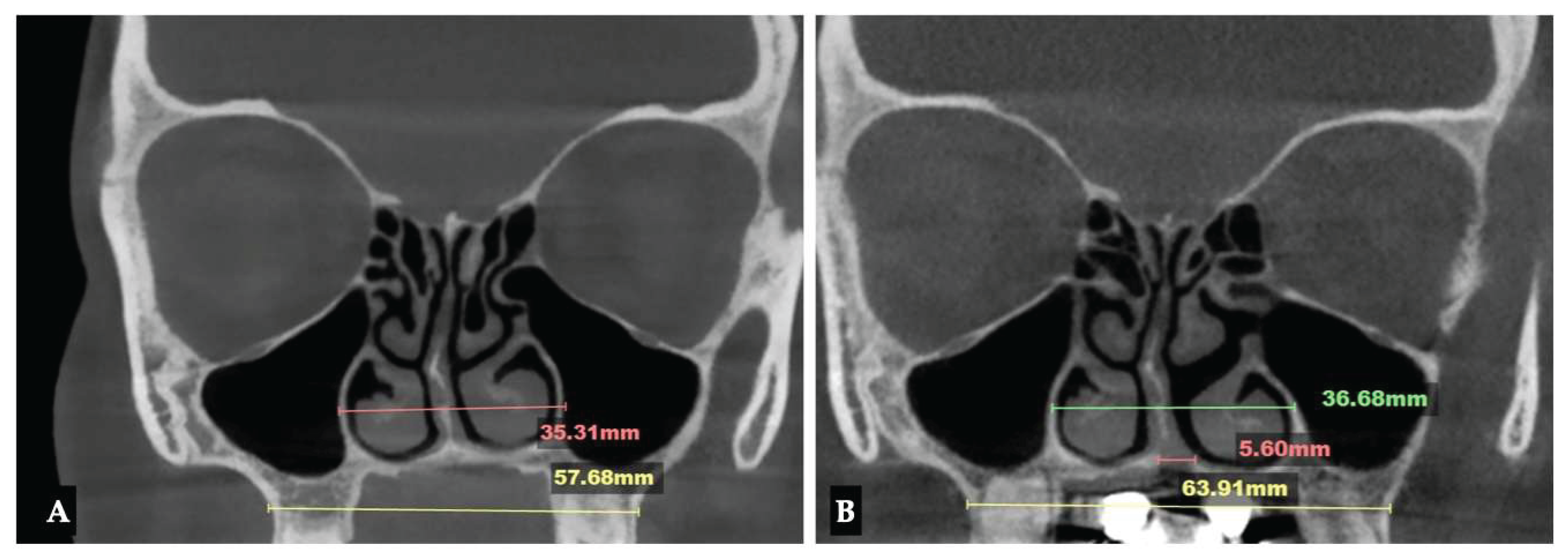
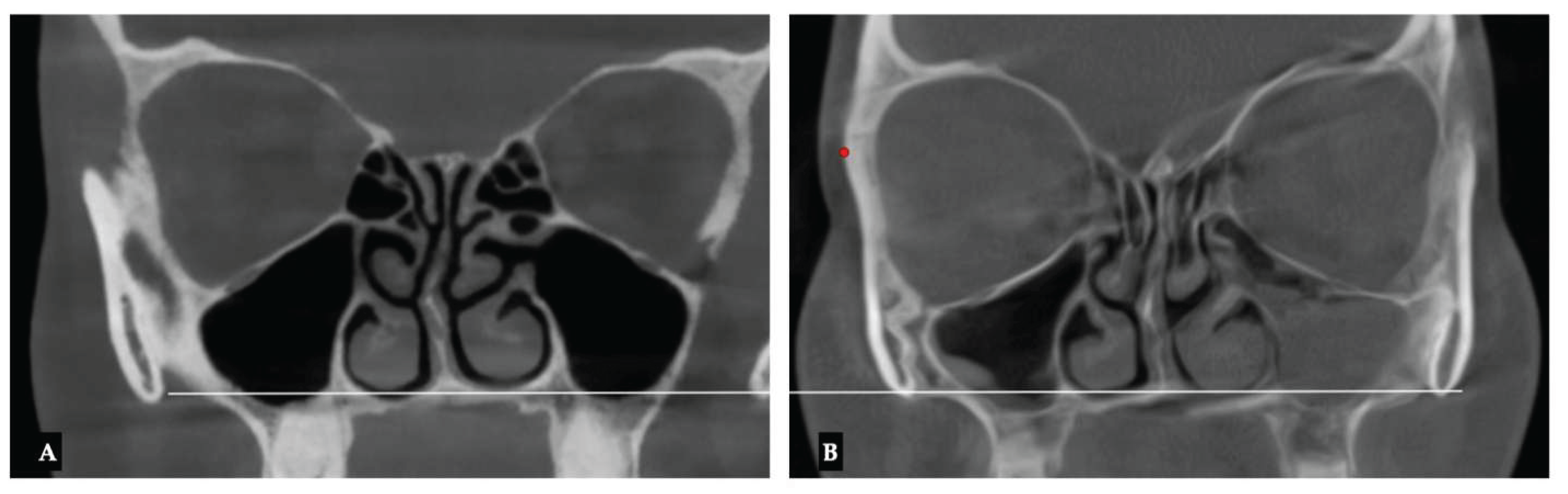
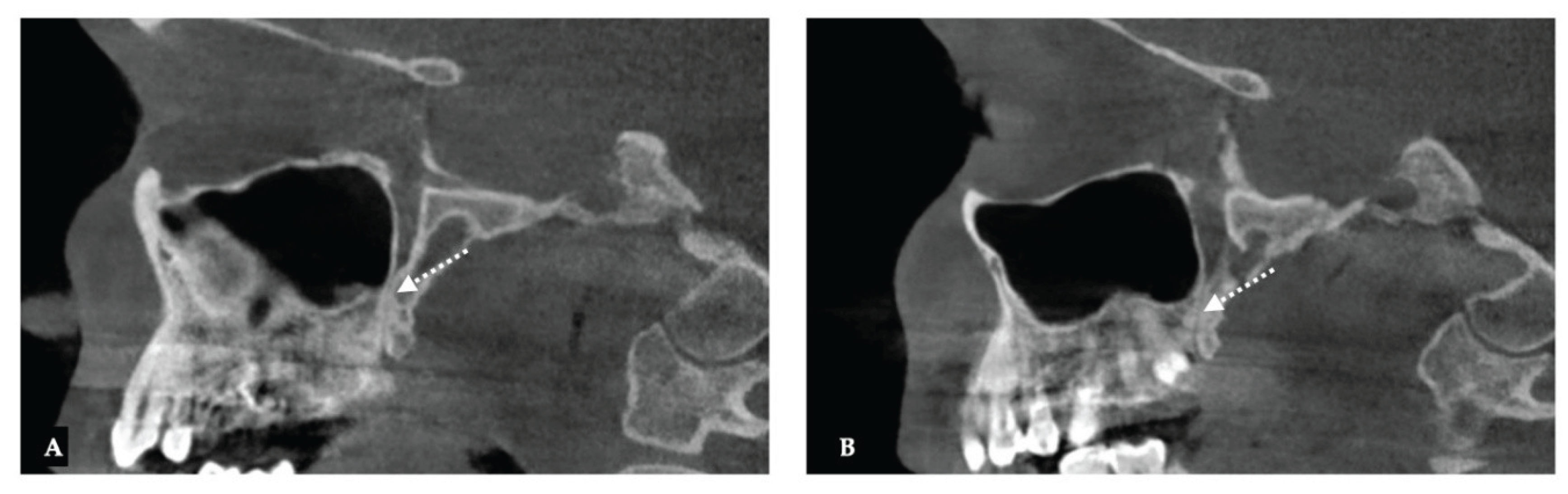
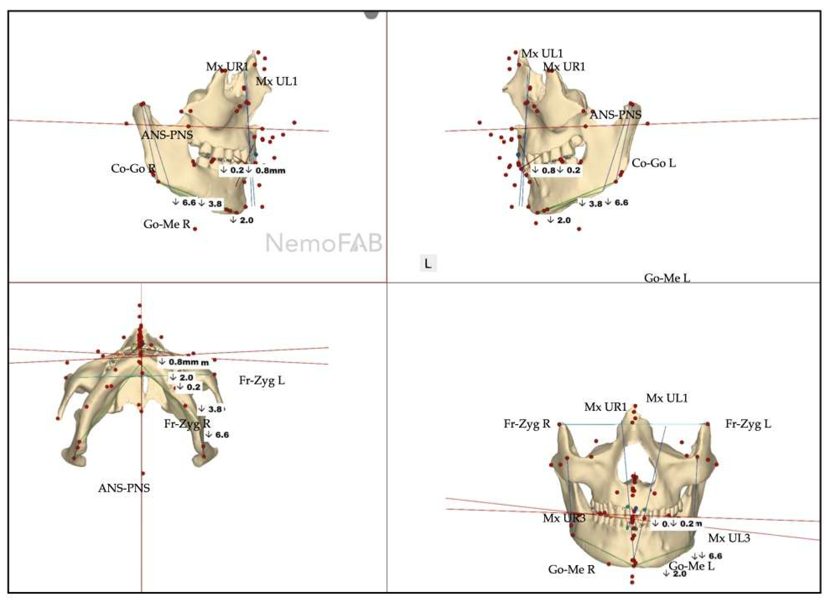
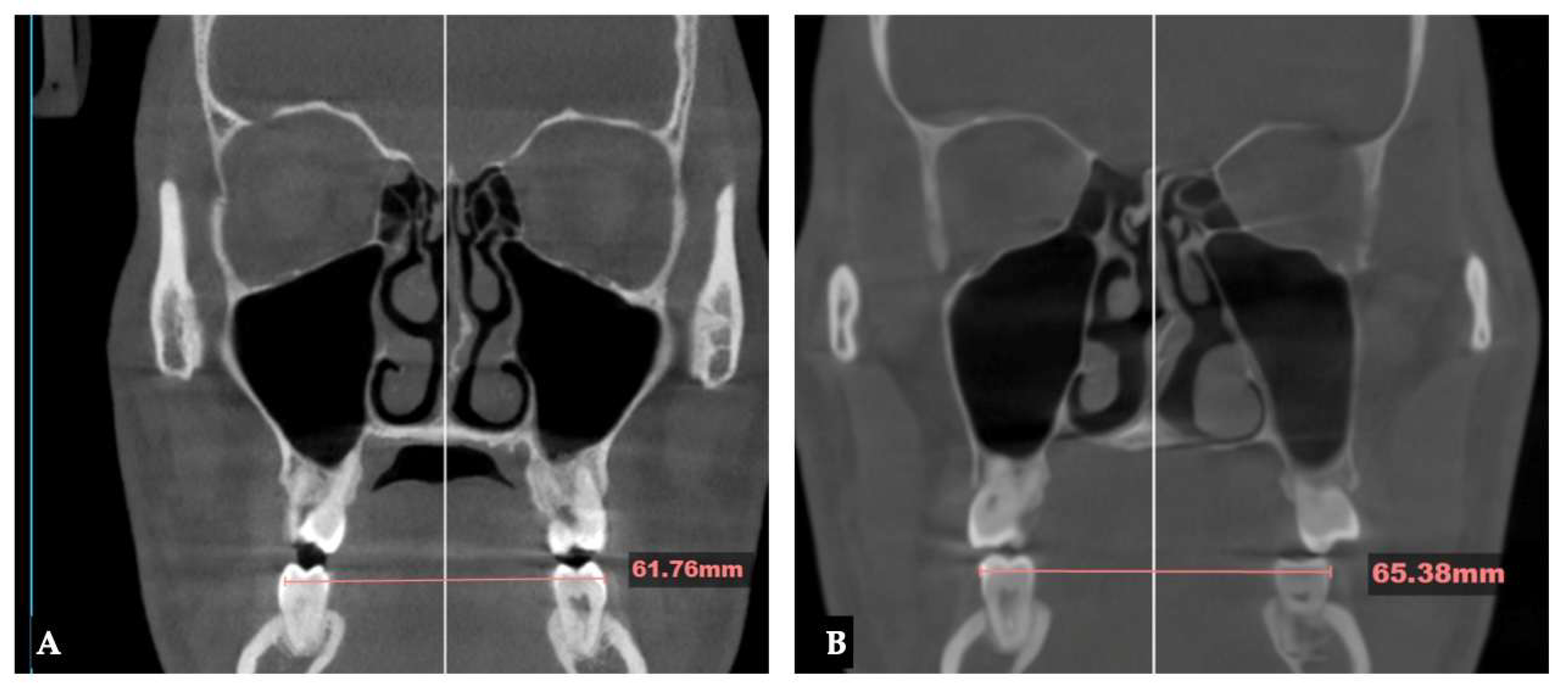
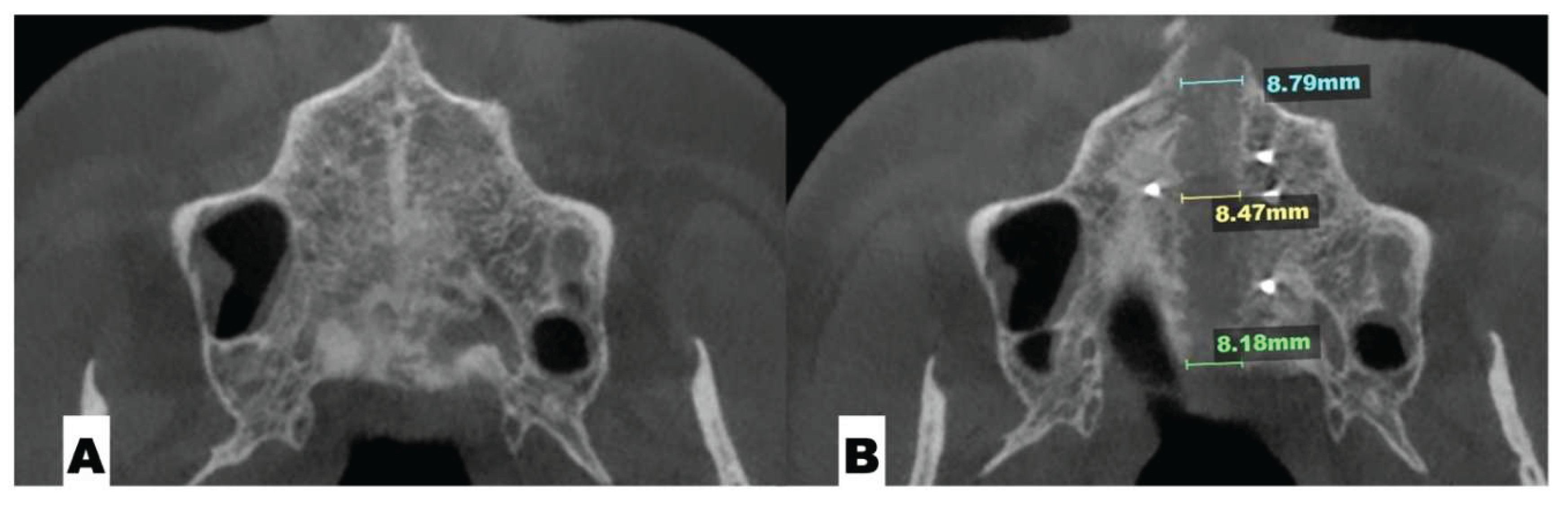
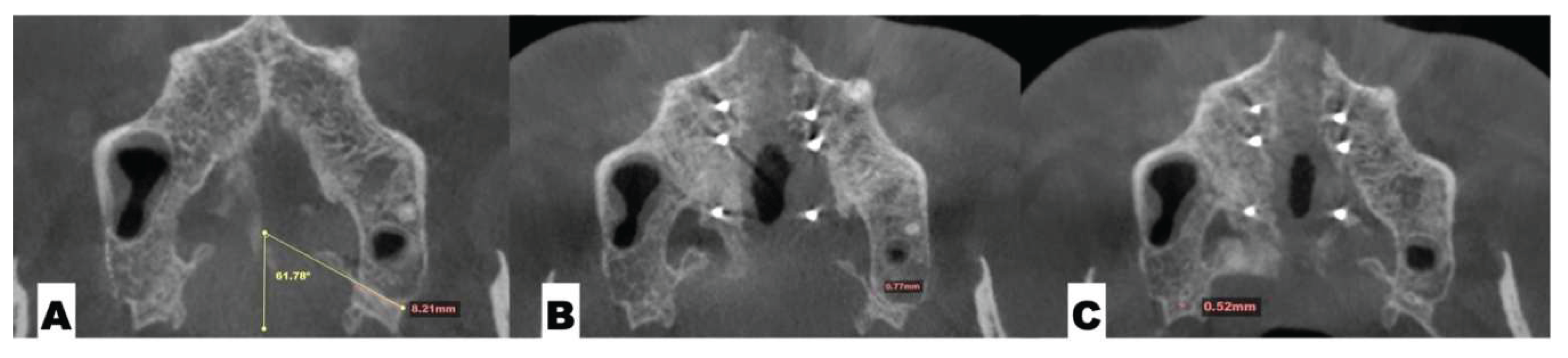
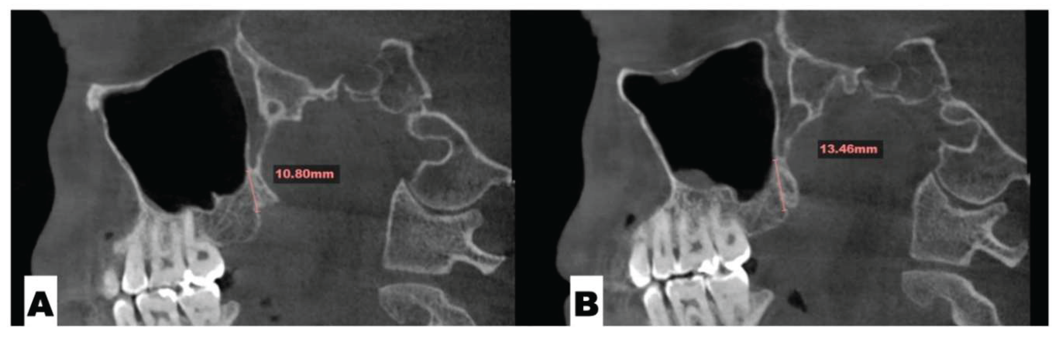
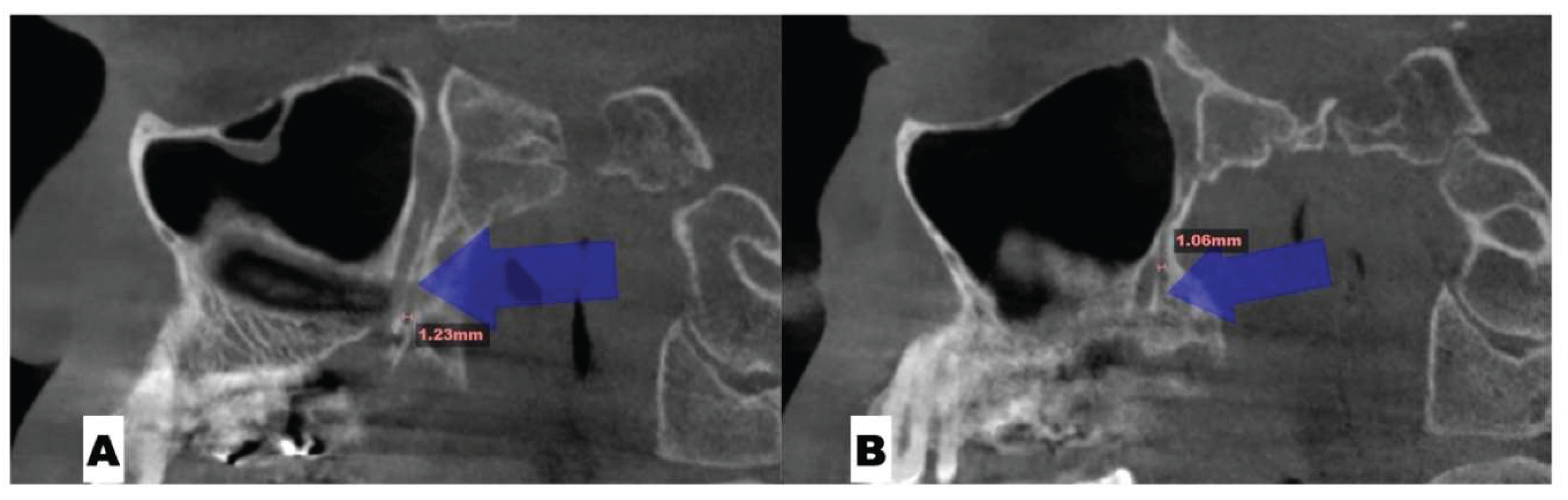
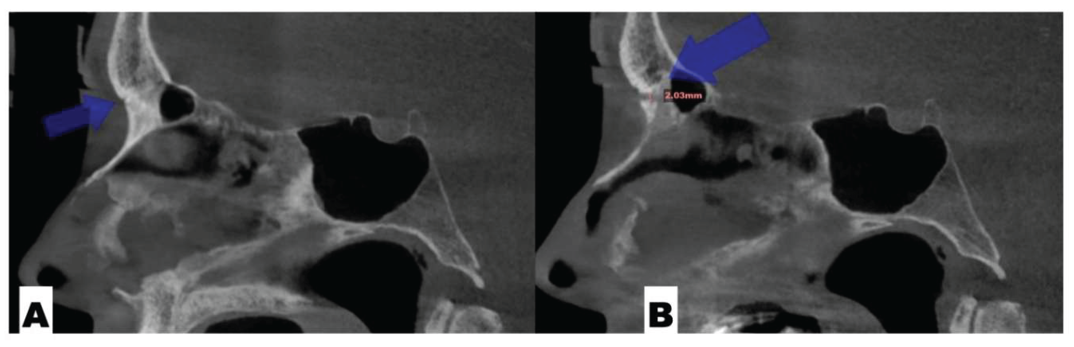
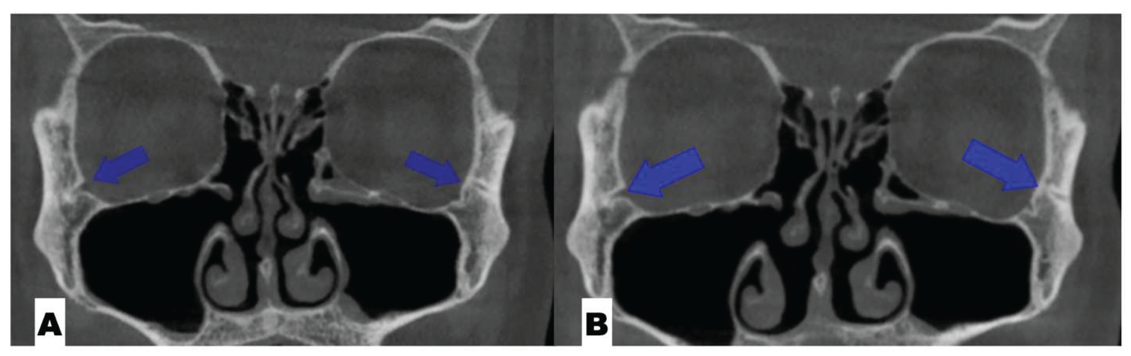
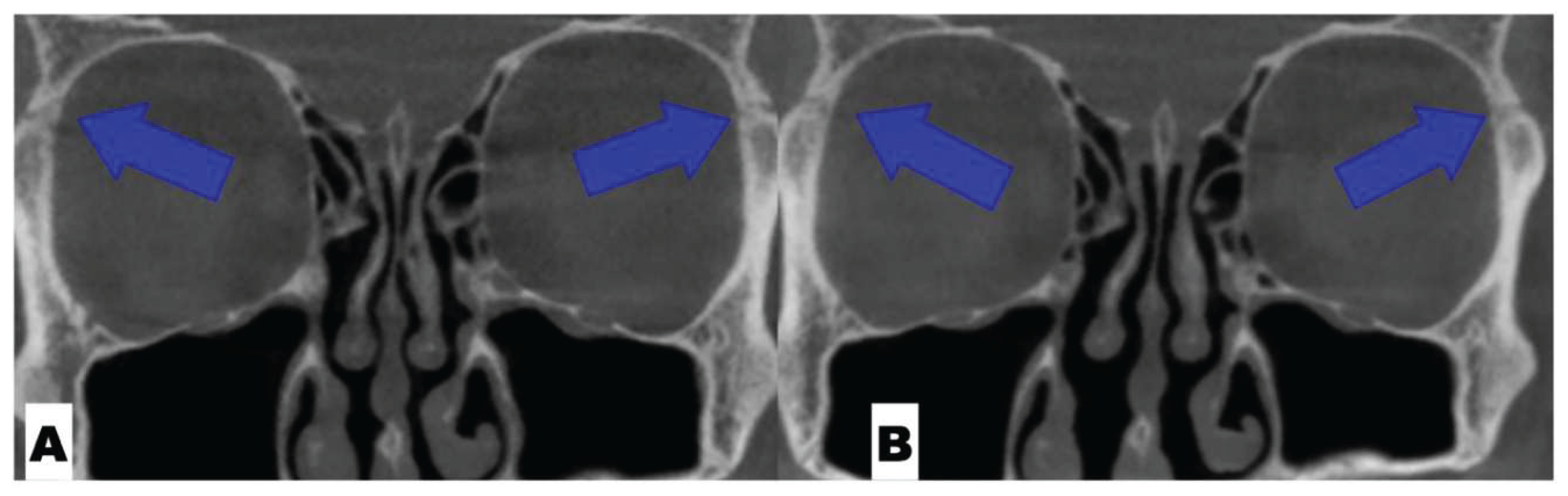
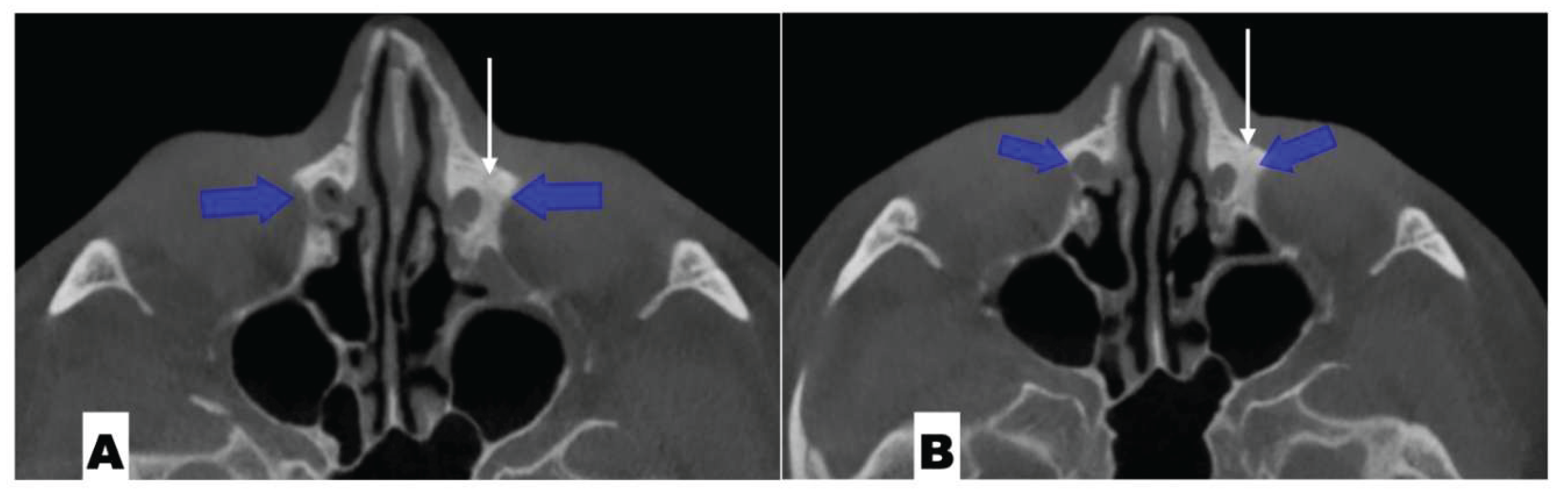
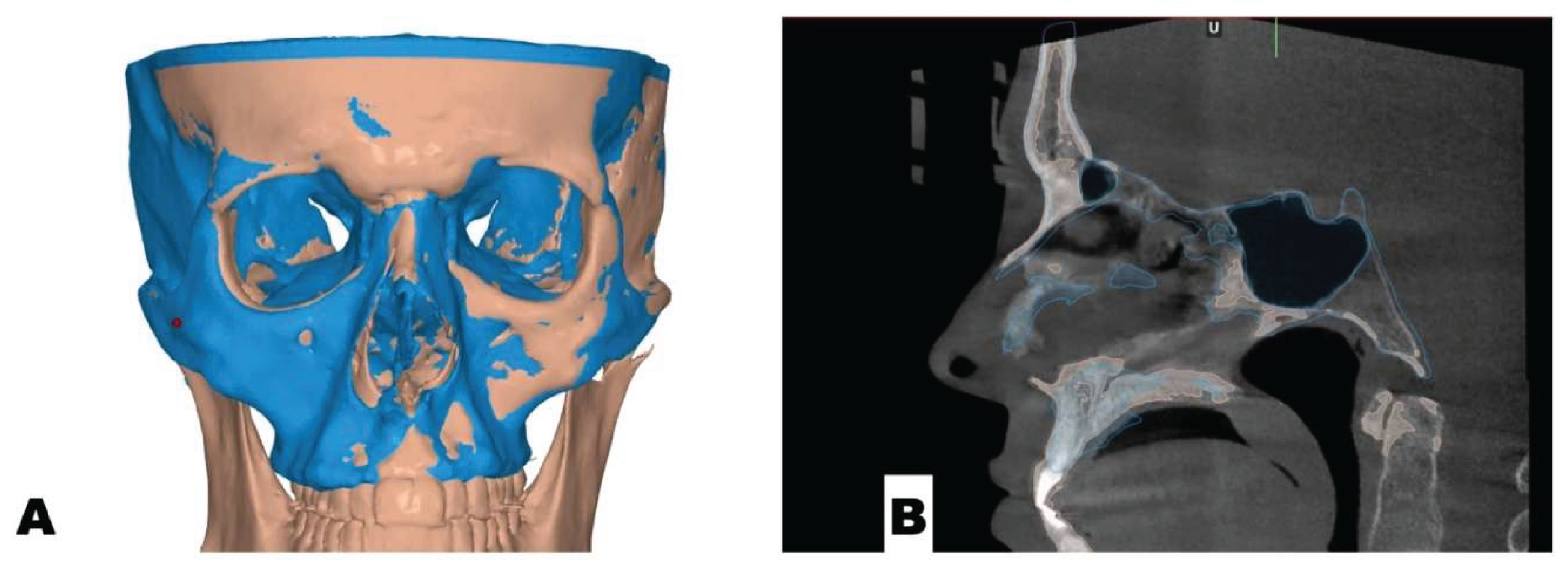
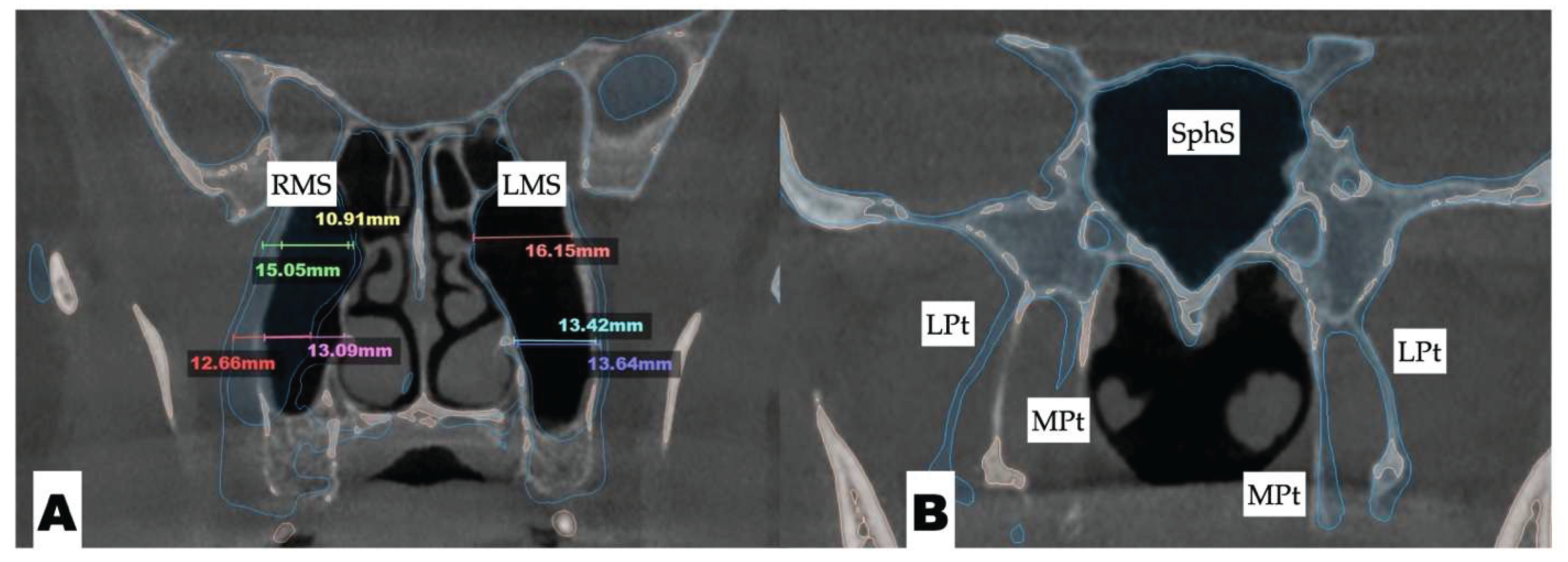
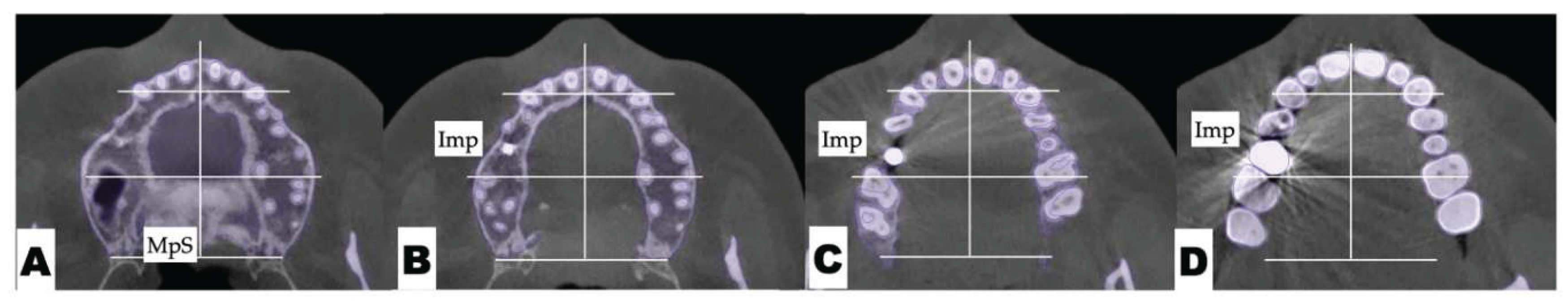
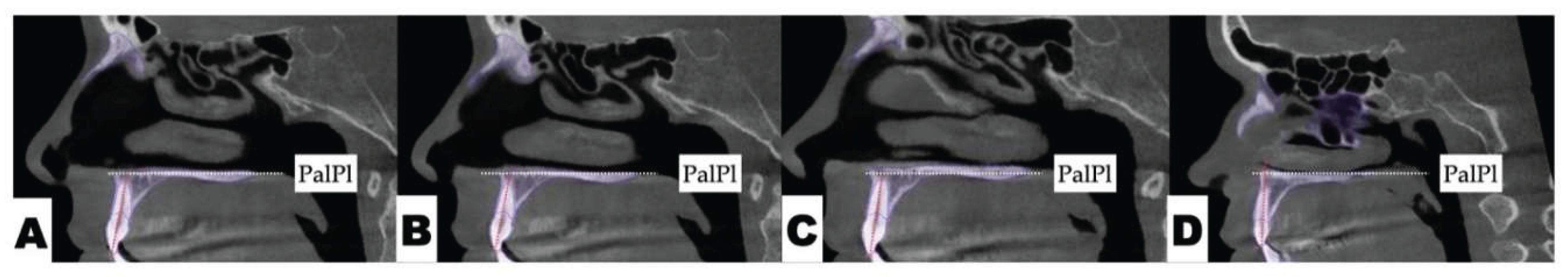
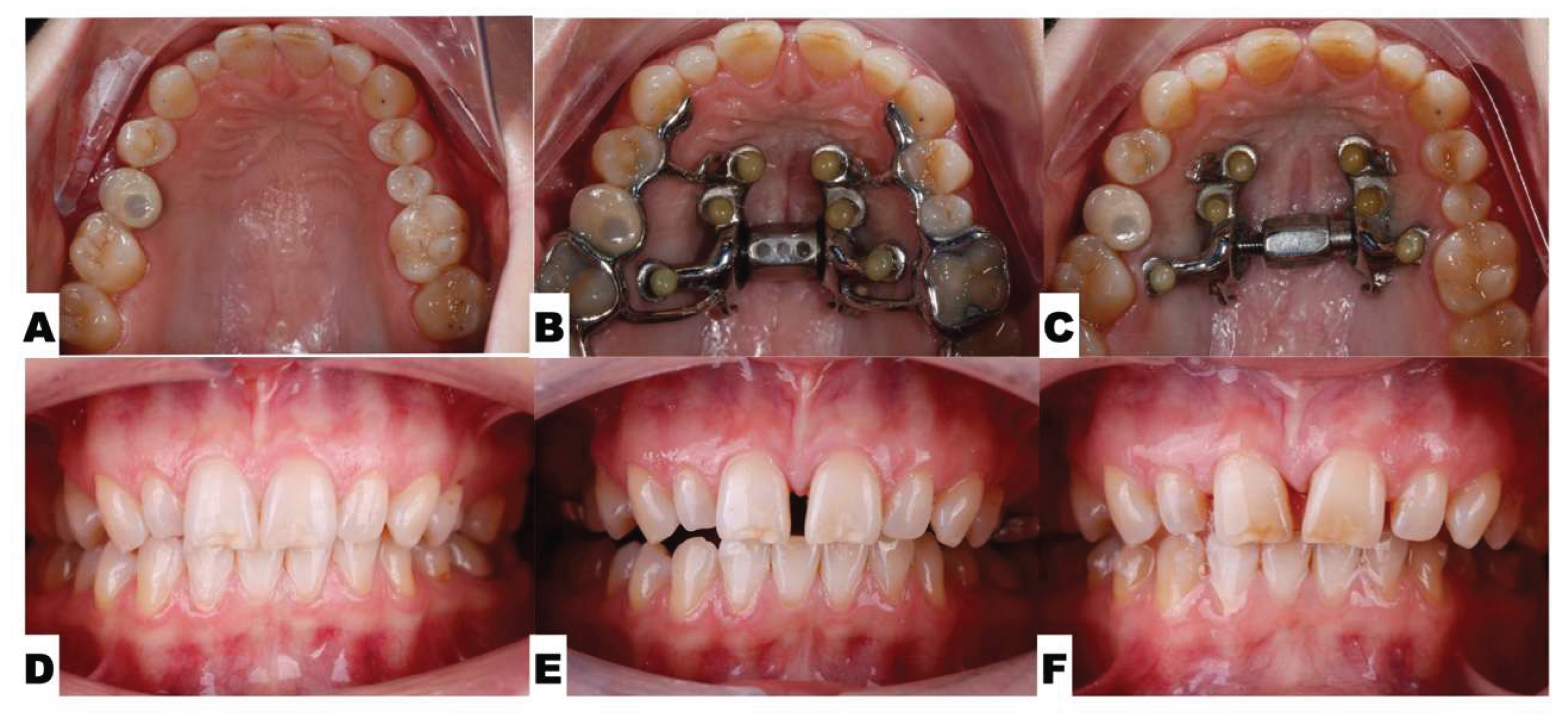
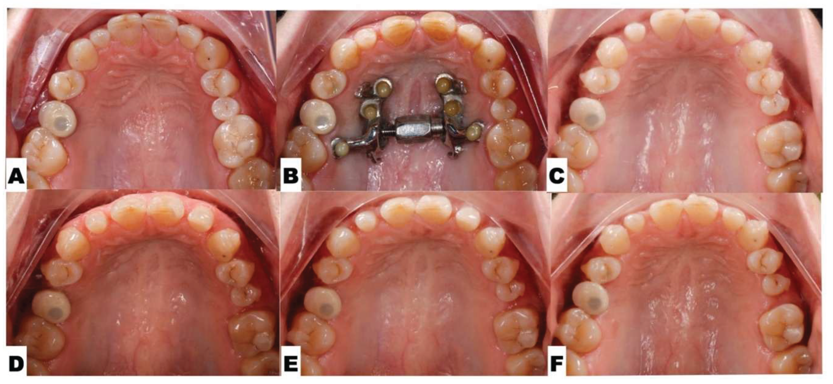
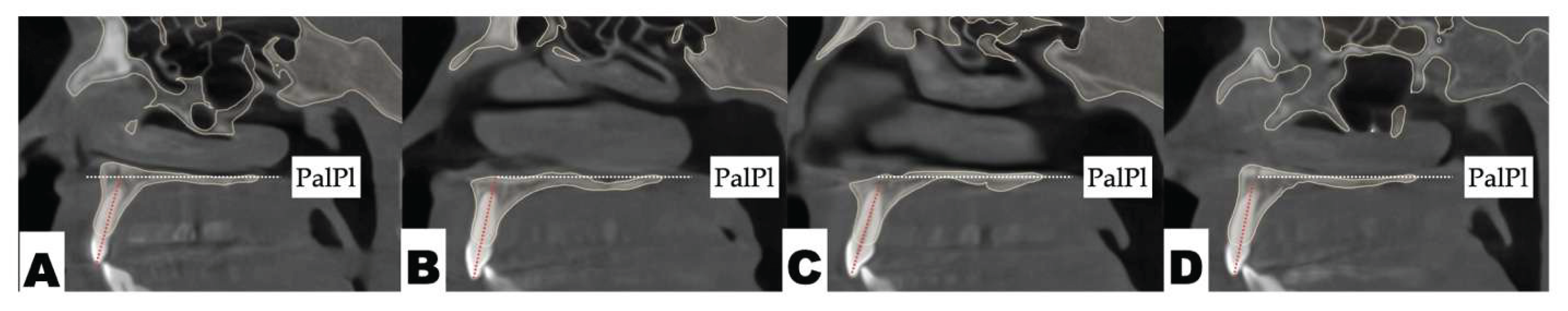
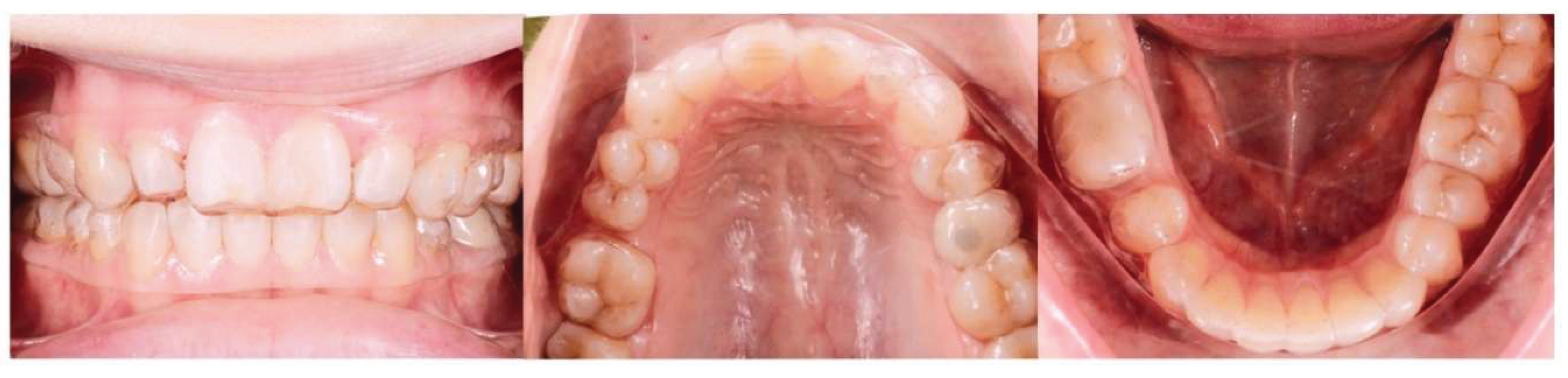
Background: While mini-screw-assisted rapid palatal expansion (MARPE) is effective for correcting maxillary transverse deficiency in adults, perimaxillary suture disarticulation—particularly at the pterygomaxillary junction—can be inconsistent. This study evaluates skeletal and dentoalveolar outcomes of a novel 3D-guided midpalatal piezocorticotomy-assisted MARPE protocol, focusing on expansion symmetry and pre-existing asymmetries. Methods: Three adult patients were retrospectively analyzed after treatment with 3D-guided midpalatal piezocorticotomy-assisted MARPE expansion and one with non-guided midpapalatal piezocorticotomy and MARPE expansion. Surgical guides were digitally designed using CBCT data to align with the nasal septum orientation in multiple planes. Perimaxillary suture disarticulation was measured pre- and post-expansion, and dentoalveolar changes were evaluated. Post-expansion asymmetries were addressed using directly printed aligners. Results: Complete midpalatal suture separation (mean 8.48 mm), involving both anterior and posterior nasal spine regions, was achieved in one patient. Bilateral pterygomaxillary disarticulation averaged 1.06–1.23 mm, resulting in forward–outward rotation of the nasomaxillary complex. Additional separation occurred at the frontonasal (2.03 mm) and vomeromaxillary (1–2 mm) sutures, with no significant changes in orbital or peri-orbital sutures. One patient presented with pre-existing dentoalveolar asymmetry, which intensified the perceived post-expansion imbalance but was successfully corrected with directly printed aligners. In the second case, 5.6 mm of suture separation resulted in a limited lateral nasal width increase (<1.5 mm), while maxillary base expansion exceeded 6 mm. A significant canine plane cant (1.2 mm) and divergent axial inclinations of the maxillary central incisors relative to the palatal plane were also observed. In the second case, a non-impactful palatal bone fracture with asymmetric displacement of the left palatine fragment was documented. After 16 months of aligner therapy, all cases exhibited favorable remodeling of the palatal structures, midpalatal suture, and alveolar processes, accompanied by improved dental alignment, occlusal plane symmetry, and mandibular dentoalveolar adaptation. The dento-alveolar expansion achieved in the third case over the course of 16 months of treatment was approximated at 4 mm. The fourth case showed consistent improvement with direct printed aligners after MARPE midpalatal diasrticulation of 11 mm after experiencing minor bone fracture. Conclusions: Human skulls exhibit considerable variability between the left and right sides, which can influence spatial balance. Pre-existing cranial asymmetries appear to be the primary contributors to asymmetry following MARPE treatment. Careful evaluation of dentoalveolar discrepancies and axial tooth inclinations is essential for preventing and managing potential asymmetric dental arch outcomes during the post-expansion phase. Although peri-maxillary bone fractures are relatively uncommon, their occurrence is influenced by multiple factors. Adjunctive techniques, such as 3D-guided midpalatal piezocorticotomy, show promise in significantly lowering the risk of intra-expansion peri-maxillary fractures.

Keywords: 
;  ;  ;  ;  ;  

Introduction

The literature reports a variety of appliance designs that are included under the definition of mini-screw-assisted rapid palatal expanders (MARPE). Most cohort studies describing the effects of mini-screw-assisted rapid palatal expanders refer to Maxillary Skeletal Expanders (MSEs). [1,2,3] The existing literature has reported that the use of an MSE is associated with significant changes in bone structure surrounding the maxillary complex, including an increase in zygomaticomaxillary width with the center of rotation of the zygomaticomaxillary complex at the proximal point of the zygomatic process of the temporal bone [2].
Maxillary suture disarticulation patterns were described in the review article by Zarate-Guerra et al. [4]. This review concludes that with mini-screw-assisted rapid palatal expansion appliances, the symmetry of perimaxillary suture disarticulation depends on pterygomaxillary suture separation and its degree. Another study by Alan et al. [5] reported significant zygomaticomaxillary downward rotation with Maxillary Skeletal Expander (MSE) appliances in a diverse group of subjects.
Studies involving the evaluation of upper airway changes with MARPE expansion have reported a significant increase in nasal airway volume and nasopharyngeal volume with treatment. Nasal septum deviation was reported to decrease with MARPE expansion [6,7].
Certain surgical approaches have been proven to improve signs and symptoms of obstructive sleep apnea. The surgical approaches with the highest efficacy were tracheostomy and maxilla-mandibular advancement surgeries. [8,9,10]. Associated side effects of MMA (Maxillo-Mandibular Advancement) surgery were described as temporary paresthesia in 85 cases, permanent hyperesthesia in 12% of cases, and successive malocclusion in 15% of cases [8]. Both articles (based on nine case series) reported high efficacy of maxilla-mandibular advancement (MMA) surgery with a mean AHI (Apnea-Hypopnea Index) reduction from 54.4 pre-op to 7.7 post-op (87%) [8,10].
MARPE and surgically assisted upper airway development (MMA, surgically assisted rapid palatal expansion (SARPE)) are both well-documented options for upper airway development in adult patients. The recently introduced 3D-guided midpalatal piezocorticotomy-assisted MARPE expansion protocol presents significant improvements regarding the predictability of Midfacial Expansion in adult patients and the symmetry of nasal floor separation [11]. The outcomes of 3D-guided midpalatal piezocorticotomy-assisted MARPE expansion are described in more detail in this article.

Materials and Methods

Study Design and Sample

A retrospective analysis was conducted on the clinical records of three patients who underwent three-dimensional (3D) guided midpalatal piezocorticotomy combined with micro-implant-assisted rapid palatal expansion (GMPA – MARPE) and one patient undergoing non-guided midpalatal piezocorticotomy assisted MARPE expansion.

Surgical Protocol

All procedures were performed under local anesthesia, initiated with topical application of 20% benzocaine, followed by infiltration of 0.5% bupivacaine (Marcaine) with 1:200,000 epinephrine into the mucosa overlying the midpalatal suture and surrounding tissues.

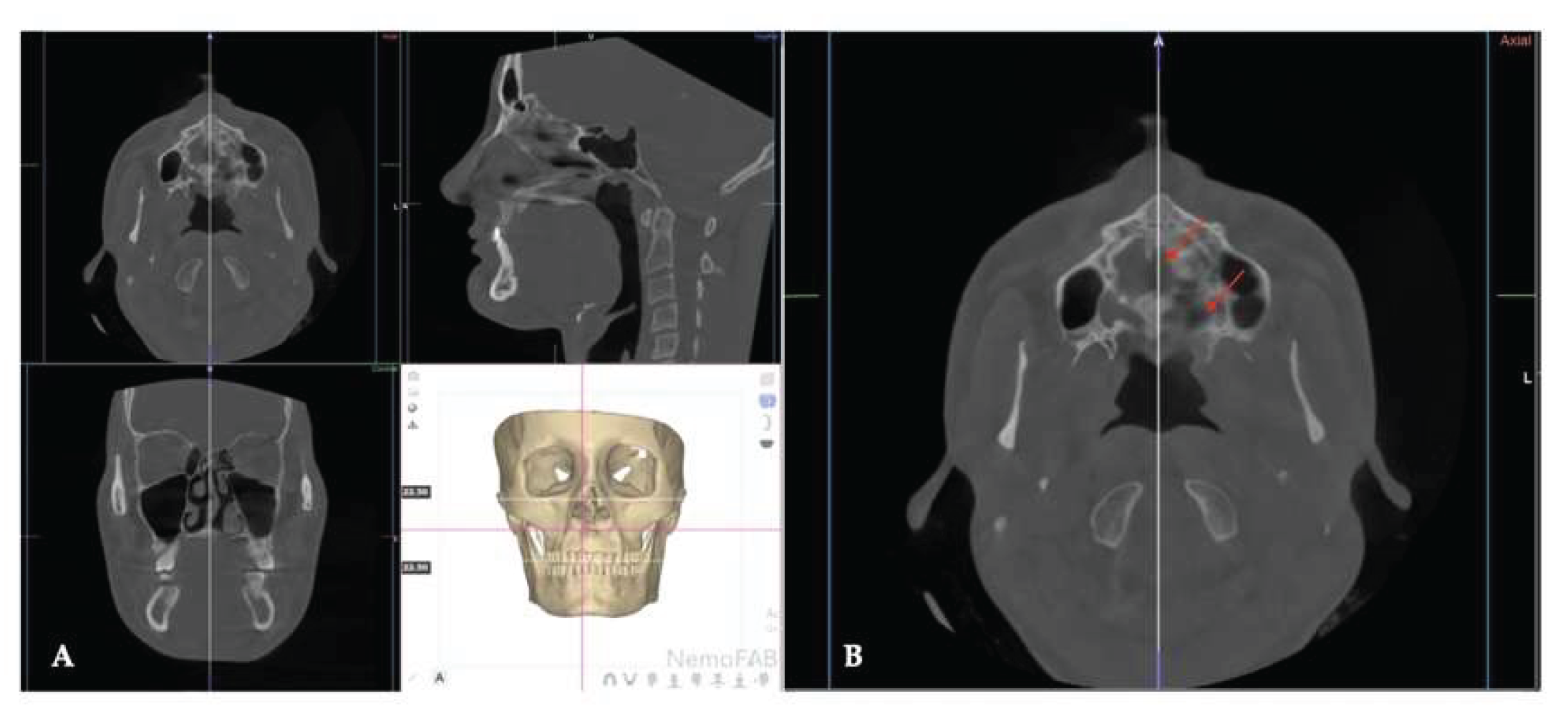
D Surgical Guide Design

A patient-specific surgical guide was fabricated using Nemocast software (Nemotec, Madrid, Spain). The guide was designed according to the anatomical position of the nasal septum in sagittal, coronal, and axial planes.

Osteotomy Planning

Piezocorticotomy cuts were individually planned for each patient to preserve approximately 10–12 mm of intact midpalatal suture anteriorly near the incisive foramen. The cuts extended posteriorly toward the posterior nasal spine (PNS), enabling midsagittal separation of the palatal processes of the maxilla and the horizontal plates of the palatine bones. One patient underwent non-guided midpalatal piezocorticotomy followed by MARPE expansion.

Patent Protection

The described 3D-guided midpalatal piezocorticotomy-assisted MARPE technique is protected under United States and Canadian patents.
Figure 1. Nasal septum orientation in axial projection before and after 3D-guided midpalatal piezocorticotomy-assisted MARPE expansion (Case 2). The 3D-guided midpalatal piezocorticotomy-assisted MARPE expansion preserves the position of the nasal septum in three planes of space with a focus on the axial plane, allowing for the symmetrical separation and movement of both pterygomaxillary sutures and an increase in the lateral nasopharyngeal wall width. A—Pre-expansion axial view of the nasal septum; B—post-expansion axial view of the nasal septum with slight improvement in its orientation.
Preprints 175625 g001

Postoperative Assessment
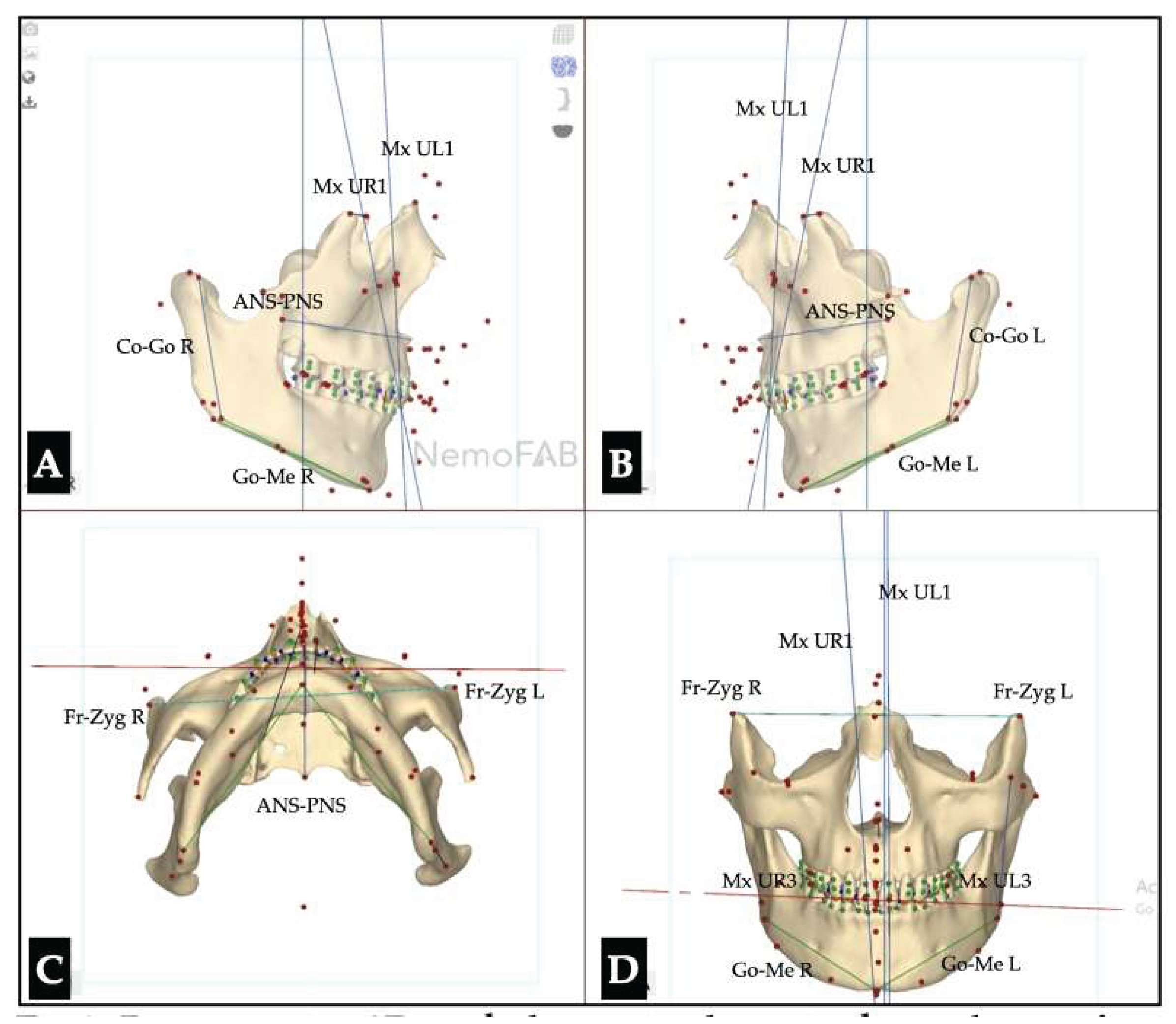
Case 1. Perimaxillary Suture Disarticulation
The maxilla is connected to the surrounding bones through the perimaxillary sutures. A number of sutures are associated with the orbit and are either located inside the orbit or compose the orbital walls. The locations and names of the perimaxillary sutures are provided in Table 1.
Other sutures (e.g., frontonasal), although not directly articulating with the maxillary bones, are also affected by 3D-guided midpalatal piezocorticotomy-assisted MARPE expansion.
The pterygomaxillary suture garners the most attention, as it represents the articulation of the maxillary bone to the cranial base along with the sphenomaxillary suture. While the sphenomaxillary suture is rarely involved in disarticulation due to its location, pterygomaxillary suture disarticulation is the desired outcome in the majority of MARPE expansion cases.
Case 1 describes the outcomes of a male patient who underwent 3D-guided midpalatal piezocorticitomy-assisted MARPE expansion. The 3D-guided piezocorticotomy was performed as per the above-described protocol, with the 10-12 mm zone mesial to the incisive foramen left unseparated. The MARPE expander was installed during the same visit under the same amount of local anesthesia. The patient was instructed to refrain from activating the appliance for the following seven days to avoid inflammation and healing complications in the area of piezocision.
Figure 2 shows the resulting expansion of the midpalatal suture following the 3D-guided midpalatal piezocorticotomy-assisted MARPE expansion. Parallel separation of the midpalatal suture, engaging both ANS and PNS regions of the midpalatal suture, was measured at an average of 8.48 mm of suture disarticulation for this patient.
The pre-expansion axial orientation and the post-expansion separation of both pterygomaxillary sutures are shown in Figure 3.
The location and length of the pterygomaxillary suture in the sagittal plane are shown in Figure 4. The orientation of the pterygomaxillary suture is uneven in all three planes of space and changes its direction in a curved manner.
The results of the disarticulation of the pterygomaxillary suture after the completion of an 8.48 mm midpalatal suture disarticulation following 3D-guided midpalatal piezocorticitomy of the midpalatal suture are shown in Figure 5.
The frontonasal suture represents the first perimaxillary suture to be disarticulated during the 3D-guided midpalatal piezocorticotomy MARPE expansion. The pre- and post-expansion frontonasal suture disarticulation is shown in Figure 6.
While changes in the frontozygomatic sutures (Figure 7) and zygomaticomaxillary sutures (Figure 8) before and after 3D-guided midpalatal piezocorticotomy MARPE expansion are negligible, intraorbital sutures undergo no to limited changes (Figure 9).
The sutures of the orbital floor include the lacrimomaxillary, zygomaticomaxillary, ethmoidomaxillary, and sphenomaxillary sutures. The diversions of the lacrimomaxillary articulation were described in the article by Raslan et al. [12]. Figure 9 shows changes in the nasolacrimal canal and its surrounding structures before and after expansion.
The total vector of perimaxillary suture disarticulation is summarized in Figure 10, and the amounts of disarticulation are shown in Table 2.
A superimposition of the skull was made relative to the structures surrounding the sphenoid sinus (Figure 10 and Figure 11).
Case 2. Preceding Dentoalveolar Asymmetry Corrected with Directly Printed Aligner Orthodontic Movements
The case described below is an example of initial dentoalveolar asymmetry resulting in aggravation of the post-expansion perception of the asymmetrical outcome.
Due to the tooth-bone-borne nature of the appliance, its placement is limited by the shape of the hard palate and its outline, the yaw of the palatal (maxillary base) plane, and its relationship to the plane connecting the posterior–superior edges of the pterygomaxillary fissure (Figure 12).
The following series of CBCT slices depicts the initial orientation of the roots of the anchoring teeth and the inclinations of the maxillary incisors relative to the buccal cortical bone, which has a significant impact on the post-expansion tooth arrangement and positions (Figure 13).
The sagittal slices of the maxillary incisors pre-expansion are depicted in Figure 14.
The following series of pre-expansion, expansion, and post-expansion maxillary occlusal views show the progress of 3D-guided piezocorticotomy MARPE expansion. Six mini-screws anchor the MARPE appliance to the bone of the palatal processes of the maxillary bones, with the framework cemented to the maxillary molars, premolars, and canines, including implant crown #4 (Figure 15).
The expansion process lasted for 8 weeks with 1 turn/day, which translates to activation of approximately 0.11 mm/turn. The pattern of midpalatal suture separation was evaluated after the completion of expansion and is shown in Figure 16. The midpalatal suture was completely disarticulated, involving both the ANS and PNS areas. The transverse palatal suture showed signs of disarticulation as well, with the left side having a larger amount of separation.
Post-expansion dentoalveolar movement progression is shown in Figure 17. The initial axial inclinations of maxillary incisors, microdontia with varying cross-sections of the maxillary incisor roots, and the pattern of disarticulation of the transverse suture all contributed to the degree of post-expansion incisor position asymmetry with perceived dominance of the buccal outline of the left maxillary segment compared to the right side. The dentoalveolar tooth positions, along with the differential initial root inclinations, were progressively corrected with directly printed aligner orthodontic movements (Thera-Hartz TA-28, Graphy, Seoul, Korea). Post-alignment axial inclinations of the maxillary incisors are shown in Figure 18.
Figure 19 shows the directly printed aligners during the pre-restorative stages of treatment.
Case 3. Vertical Dento-Alveolar Discrepancy Impact on the Outcomes of the GMPA - MARPE Expansion in an Adult Patient
Pre—and postoperative skulls were oriented relative to the infraorbital line in coronal plane, ANS-PNS plane in axial plane, and relative to the Frankfurt horizontal in sagittal plane in NemoFab software (NemoFab, Nemotec, Madrid, Spain). (Figure 1) Pre-operative view shows initial mandibular roll and yaw associated with the maxillary vertical discrepancy.
Figure 1. Pre-operative skull orientation in three planes of space. A- Orientation of the skull in sagittal plane, right side view. B- Skull orientation in sagittal plane, left side view. C- Skull orientation in axial view. D- Skull orientation in coronal plane. Or - Orbit, ANS - Anterior Nasal Spine, PNA- Posterior Nasal Spine.
Preprints 175625 g020
Figure 2. Pre-operative 3D cephalometric planes in three planes of space. A- Orientation of the skull in sagittal plane, right side view. B- Skull orientation in sagittal plane, left side view. C- Skull orientation in axial view. D- Skull orientation in coronal plane. Mx UR1 - vertical axis of the Maxillary right central incisor, Mx UL1 - vertical axis of the Maxillary left central incisor, ANS-PNS - maxillary base plane, Go-Me R - body of the mandible length right, Go-Me L - body of the mandible length left, Co-Go R - right mandibular ramus length, Co - Go L - left mandibular ramus length, Fr -Zyg R - front-zygomatic suture right, Fr- Zyg L - front-zygomatic suture left, Mx UR3 - Maxillary right canine cusp tip, Max UL3 - Maxillary left canine cusp tip.
Preprints 175625 g021
3D cephalometric measurements were calculated for the assessment of the cant of maxillary and mandibular occlusal and skeletal planes according to Arnett 3D cephalometric analysis. [13,14] (Table 1, Figure 3.)
Figure 3. 3D cephalometric cant measurements in three planes based on the Arnett 3D cephalometric analysis. A- Orientation of the skull in sagittal plane, right side view. B- Skull orientation in sagittal plane, left side view. C- Skull orientation in axial view. D- Skull orientation in coronal plane. Significant maximally canine plane cant is evident with the left side located below the right side with the difference of 1.2 mm. The cant of the mandibular canine plane is inclined 0.3 mm down on the right side.
Preprints 175625 g022
Table 1. Cant assessment in 3D cephalometric analysis. Maxillary canine plane, chin cant, mandibular body cant, and 2nd molar cant show significant inclination downward on the left side.
Maxillary canine plane -1.2 L
Mandibular canine plane 0.3 R
Chin cant -0.9 L
Body cant -1.6 L
Gonion cant 0.2 R
2nd molar cant -0.4 L
As seen on Figure 3, the inclinations of both vertical axes of the maxillary central incisors differ relative to the Palatal plane (ANS-PNS). The axis of the left maxillary central incisor is steeper with grater proximity of the tooth root apex to the maxillary buccal cortical plate.
Figure 4 and 5 depict the impact of the midpalatal suture disarticulation on the lateral nasal width and the maxillary base width. In particular, with 5.6 mm of midpalatal suture disarticulation the amount of lateral nasal width increase did not exceed 1.5 mm. The maxillary base increase, on the opposite, exceeded 6 mm.
Figure 4. Pre- (A) and post- (B) expansion maxillary base width, lateral nasal width, and the amount of expansion at the level of the nasal base width in projection of the maxillary first molars. The Total amount of midpalatal suture disarticulation is 5.6 mm, the lateral nasal width changed form 35.3 mm to 36.68 mm; maxillary base width increased from 57.68 to 63.91 mm ( 6.23 mm difference).
Preprints 175625 g023
Figure 5. Pre-treatment (A) and twelve (12) months after completion expansion (B). Nasal base orientation relative to the alveolar processes and base of the skull. Both pre- and post-operative CBCT scans are oriented relative to the True Vertical Line (TVL) and Frankfurt Horizontal (FH).
Preprints 175625 g024
Figure 6 confirms the disarticulation of the pterygomaxillary suture on both sides, while Figure 5 shows little-to-no change in the inclination (cant) of the nasal base plane) in longterm. Figure 7 is a visual description of changes happening to the nasal base and teeth located in the closer proximity to the midpalatal suture. As seen on the same Figure, the axis of tooth #9 significantly changed in coronal plane due its initial axis inclination engaging the buccal cortical plate of the maxillary alveolar process. Table 2 shows difference between the initial and post-expansion cants of maxillary and mandibular canines and mandibular bone structures.
Figure 6. Post- expansion (immediately) disarticulation of both pterygomaxillary sutures. A - Right side, B - Left side.
Preprints 175625 g025
Figure 7. Post-operative 3D cephalometric planes in three planes of space. A- Orientation of the skull in sagittal plane, right side view. B- Skull orientation in sagittal plane, left side view. C- Skull orientation in axial view. D- Skull orientation in coronal plane. Mx UR1 - vertical axis of the Maxillary right central incisor, Mx UL1 - vertical axis of the Maxillary left central incisor, ANS-PNS - maxillary base plane, Go-Me R - body of the mandible length right, Go-Me L - body of the mandible length left, Co-Go R - right mandibular ramus length, Co - Go L - left mandibular ramus length, Fr -Zyg R - front-zygomatic suture right, Fr- Zyg L - front-zygomatic suture left, Mx UR3 - Maxillary right canine cusp tip, Max UL3 - Maxillary left canine cusp tip.
Preprints 175625 g026
Table 2. Cant assessment in 3D cephalometric analysis immediately after expansion. Maxillary canine plane, chin cant, mandibular body cant, and Gonion cant have increase favoring left side.
Parameter Before Expansion After Expansion
Maxillary canine plane -1.2 L -4.1 L
Mandibular canine plane 0.3 R -1.1 L
Chin cant -0.9 L -2.0 L
Body cant -1.6 L -3.8 L
Gonion cant 0.2 R -5.3 L
2nd molar cant -0.4 L -0.4 L
Figure 8 is a visual representation of the changes associated with the midpalatal disarticulation associated with the differential maxillary incisor axis orientation. Maxillary canine cant is evident on both pre- and post-expansion frontal occlusal photographs.
Figure 8. Before (A) and immediately after (B) expansion frontal view of the maxillary canine cant. With 5.6 mm of disarticulation of the mid palatal suture at the level of the nasal base in projection of the maxillary first molars and pterygomaxillary suture disarticulation, maxillary canine cant aggravation is detected following the direction of the initial maxillary canine cant. The maxillary left side underwent vertical dento-alveolar migration.
Preprints 175625 g027
Case 4. Peri-Maxillary Bone Fractures Associated with MARPE Expansion and No 3D Guided Midpalatal Piezoxorticotomy
The following case is a presentation of the 27 yo. male patient undergoing MARPE expansion without guided piezocorticotomy. The patient presented with skeletal Class III jaw relationship and a brachyfacial facial type. CBCT was taken at three time points - before expansion (start of treatment), 4 months after treatment initiation (two months of MARPE expansion completed), and 12 months after the completion of MARPE expansion during aligner tooth movements.
CBCTs at all three timepoints were taken in a natural head position (NHP) and further skulls re-oriented in a NemoFab (Nemotec, Madrid, Spain) software according to three planes: orbital plane, Frankfort Horizontal, and ANS-PNS planes. Figure 9 demonstrates skull orientation all at three timepoints.
Figure 9. Skull alignment and orientation at each stage of MARPE expansion. No guided piezocorticotomy executed in this case. A - Before Expansion. B - 4 months after the beginning of treatment. C - 16 months after the beginning of treatment. At all timepoints skull was oriented relative to three planes: orbital plane, Frankfort horizontal, ANS-PNS plane.
Preprints 175625 g028
Figure 10 follows the same skull orientation and demonstrates the course of the transverse suture.
Figure 10. Pre-treatment orientation of the transverse suture and horizontal plates of the palatine bones. A - Skull orientation in three planes of specs relative to three planes: Or-Or (Infraorbital plane), ANS - PNS, and Frankfort Horizontal. A - Skull orientation in three panes of space. B - Close up axial view of the palatal bones with the transverse suture and the interpalatine suture.
Preprints 175625 g029
Figure 11 and 12 are two consecutive stages, 4 months from the beginning of treatment with completed MARPE expansion and at 16 months of treatment. Fracture of the left palatine bone is evident on Figure 11, while Figure 12 shows successful remodeling, improved teeth arrangement, palatal plane alignment and improved nasal septum position.
Figure 11. Four (4) months after the beginning of treatment with 2 months of expansion complete. Appliance design is similar to the previously shown designs. The total amount of 11.6 mm of parallel separation of the mid palatal suture is evident on Figure 11 A. B - Close up axial view of the palate with the 11. 6 mm of midpalatal suture disarticulation up until the transverse suture. C - fracture within the horizontal plate of the left palatine bone and no separation of the interpalatine suture.
Preprints 175625 g030
Figure 12. Sixteen (16) months since the beginning of treatment with 12 months since the expansion completion. A - skull orientation is consistent with two other CBCTs taken at 0, and 4 months of treatment, respectively. B - Close up axial view of the palate demonstrating near complete ossification of the palatal processes fusion at the midplatal junction and residual remodeling in the middle third of the palate. The remodeling is also evident at the level of the fracture of the left palatine bone. (Arrows).
Preprints 175625 g031
While this case is a demonstration of the non- impactful bone fracture with some degree of asymmetric displacement of the left palatine fractured piece with the corresponding alveolar process on the left side, at 16 months of aligner treatment significant improvement is visible in both remodeling of the palatal processes, midpalatal suture and fractured fragments of the paltien bone. Additional improvements are visible in teeth arrangement and alignment of the occlusal planes of both arches following dento-alveolar movements and mandibular dento-alveolar expansion with surface remodeling (Figure 13).
Figure 13. Mandibular width measured at the level of the buccal surface soft 2nd mandibular molars with consistent head orientation. A - Before MARPE expansion. B - 16 months after the beginning of treatment with MARPE expansion and aligner mandibular dente-alveolar expansion and surface remodeling. Almost 4 mm or mandiabular expansion was achieved up to the depicted stage of treatment.
Preprints 175625 g032

3. Discussion

Maxillary skeletal expansion was shown to serve indications other than correction of cross-bite malocclusions, narrow maxilla, and high-vaulted palate. Recent study has shown that Maxillary Skeletal expansion in pediatric patients significantly improved nasal breathing based on subjective data (SN5 questionnaire) and objective measurements of nasal airflow and resistance. [15]
MARPE expansion has become a widely accepted technique showing promising results in improving upper airway size and dimensions [16,17]. Liu and coauthors have shown that nasal cavity width, alar width and upper airway volumetric characteristics improve with MARPE expansion. Some studies demonstrate lower rates of MARPE success (84.6%) due to difference in appliance design, fabrication process, and associated auxiliary procedures. [18] Dental and skeletal effects of MARPE expansion were described by McMullen and coauthors [19] showing similar forward and downward displacement of ANS and maxillary canines in growing and non-growing patients. This is in agreement with our observation of vertical dento - alveolar changes, particularly, in maxillary canine area.
In a review article by Zarate-Guerra [20], the authors analyzed thirteen published studies and evaluated the impacts of perimaxillary suture separation on expansion patterns. The authors evaluated the results of expansion with Maxillary Skeletal Expander (MSE) appliances in young and young adult patients. They concluded that, based on the results of several studies, uneven separation of the pterygomaxillary suture may contribute to the deviation in the disjunction of the midpalatal suture at the level of the ANS. While this case report is focused on adult patients with completed growth and a different procedure design (3D-guided midpalatal piezocorticitomy-assisted MARPE expansion, compared to MSE appliance alone), the results of both studies are in agreement regarding the involvement of the pterygomaxillary suture along with other perimaxillary sutures. The pterygomaxillary suture, thus, is impacted by the midpalatal disarticulation: young patients and young adult patients were shown to experience midpalatal separation with pterygomaxillary disarticulation, while adult patients with completed growth also experience pterygomaxillary disarticulation with 3D-guided midpalatal piezocorticotomy-assisted MARPE expansion and without direct manipulations on the pterygomaxillary suture.
Another study assessing the outcomes of MSE appliances concluded that the Maxillary Skeletal Expander in young adults (mean age 18+/- 3years) produced relatively parallel separation of the midpalatal suture with 84% of separation of the pterygomaxillary sutures [21]. A study by Cantarella and colleagues [22] confirmed the possibility of asymmetric pterygomaxillary suture separation in adolescents with the MSE appliance. The authors evaluated the symmetry of the midpalatal suture opening by comparing the deviation of the ANS point from the midline on both sides.
Our study evaluated the impact of the greater amounts of expansion achieved with 3D-guided midpalatal piezocorticitomy-assisted MARPE expansion (8.48 mm) measured between the maxillary crests of the palatient processes of the maxillary bones in axial plane, compared to an average 4.3 mm midpalatal separation in similar studies without 3D-guided midpalatal piezocorticotomy and other appliance designs. The behavior of the ANS point once split [21,22] was used as the reference for evaluating the symmetry of midpalatal expansion, while the pattern of separation with both approaches involves a similar mechanism of separation of this residual area and a high probability of bone microfractures and remodeling due to the proximity of the maxillary incisor roots and the overall area topography.
This research suggests that midpalatal disarticulation, evaluated in the axial plane, offers the most accurate representation of maxillary skeletal expansion. This approach contrasts with the previously described method that was used to evaluate the amount of maxillary expansion [23,24], who used maxillary first molars as reference points for assessing expansion. The rationale for employing skeletal rather than dental reference landmarks is to minimize inaccuracies associated with molar tipping, which constitutes a significant proportion of the overall transverse change, particularly in cases treated with tooth-bone–borne expansion appliances [25]. Future research should therefore prioritize imaging techniques that capture skeletal landmarks directly, in order to achieve more reliable and clinically meaningful assessments of maxillary expansion.
The methodology of pterygomaxillary suture analysis was described by Tunis et al. [26]. Particular interest in this study was attributed to disarticulation of the pterygomaxillary suture, which was used as guidance in the current study. According to Tanne et al. [27], the center of resistance of the nasomaxillary complex is located at the posterior–superior edge of the pterygomaxillary fissure. According to Sneha et al. [28], the vertical height of the pterygomaxillary fissure varies between sexes and averages at 22.68 and 22.34 mm in males and females, respectively. The current case report shows evidence of pterygomaxillary suture separation in an adult male patient pursuant to the 3D-guided midpalatal piezocorticotomy-assisted MARPE expansion. The disarticulation is located along the posterior wall of the maxillary sinus at the level of the junction between the pterygoid process of the sphenoid bone constituting the lateral wall of the fossa pterygopalatine.
The involvement of the orbit in mini-screw-assisted rapid palatal expansion was described by Shi and coauthors [29]. The authors concluded that the dimensions of the orbit increased along with the increase in width between the right and left zygomaticomaxillary sutures (1.69+/- 0.57 mm) and, to a lesser degree, the increase in width between the right and left frontozygomatic sutures (0.15 +/- 0.32 mm). The current study has noted no significant changes in the width of either the frontozygomatic or zygomaticomaxillary suture alone. The above-mentioned sutures constitute the lateral wall of the orbit, while other sutures, such as zygomaticomaxillary, lacrimomaxillary, ethmoidomaxillary, and sphenomaxillary, are found along the orbital floor and the medial and posterior orbital walls. Any changes in orientation of the above-mentioned sutures play a significant role in the orientation of the enclosed structures of the orbit. Diversions of the lacrimomaxillary articulation were described in the article by Raslan and coauthors [12]. In our study, we did not find any changes in the lacrimomaxillary articulations on either side. Baser and coauthors [30] did not find any significant changes in the optic nerve sheath diameter evaluated under ultrasonography guidance.
Article by Cho and coauthors [31] evaluated peri-maxillary suture changes in non-growing young adult patients undergoing MARPE expansion. This research article confirm that disarticulation takes place in nine (9) peri-maxillary sutures with the highest degrees of separation in fronto-maxiallry, naso-maxillary,and fronto-nasal sutures. This is in agreement with the present case report and the earlier published case report presenting a case of adult GMPA-MARPE expansion with a midpalatal disarticulation averaging 8.46 mm.
Short-term study of the soft tissue changes following MARPE expansion as concluded that peri-nasal soft tissues undergo changes with associated increase in nasal width, and downward and forward movement of the nasal landmarks. [32] Due to close proximity of the nasal soft tissue landmarks to the dento- alveolar landmarks, our observations have concluded that nasal soft tissue undergo changes throughout orthodontic treatment following MARPE expansion as well.
A superimposition of the skull was made relative to the structures surrounding the sphenoid sinus [33]. Superimpositions were performed to identify the direction and amount of midfacial movement as a result of the intervention. Our study is in agreement with earlier published studies reporting the outward vector of the zygomaticomaxillary rotation [34].
Case 2 describes an approach to pre-expansion assessment of the maxillary root orientation in three planes, with an emphasis on the proximity and angulation relative to the buccal cortical plate. Post-expansion orthodontic treatment lacks descriptive studies and is limited to case reports. Bud and colleagues described side effects of the MARPE expansion with and without corticopuncture [35] and reported occlusal modifications that occur post-expansion that are related to asymmetrical occlusal relationships prior to the beginning of treatment. The current case study shows the results of dentoalveolar root torque correction following 3D-guided midpalatal piezocorticitomy-assisted MARPE expansion, along with tooth movements with directly printed aligners (DPAs). The efficacy of the DPA has been shown in multiple studies [36,37,38], which describe their higher accuracy, precision, efficacy, and shape-memory effects. DPAs with shape-memory effects were used for post-expansion orthodontic treatment in both cases to facilitate and improve the quality of orthodontic tooth movements post-expansion. For both cases, NemoCast (Nemotec, Madrid, Spain) planning software was used to plan orthodontic tooth movements and allow precise positioning of the roots by merging intraoral scans and CBCTs.
MARPE – related asymmetries were examined in several studies , where no asymmetries were observed in MARPE group [39] and both RPE (Rapid Palatal Expander) and MARPE groups showed similar results in ability to increase the nasal base width, maxillary base width, inter-zygomatic width.
Skeletal asymmetries of the midface are common and might be related to different conditions. One of the conditions that presents with orbital asymmetry is the Unilateral Cleft Lip and Palate (UCLP) that was shown to present with unilateral orbital asymmetry. [40] Anatomical variability of the human orbit presents itself with, on average, 0.8 mL volume difference between right and left sides, and up to 200% skull-to-skull orbital volume range. [41] This has a significant implication on referring to the contralateral side during orthognathic reconstruction surgeries or with MARPE expansion procedures. While Frankfurt Horizontal and True Vertical Planes are still widely used for skull orientation and measurements it might be questionable which side to use as a reference with 3D skull orientation. Barbera et al. [42], thus, suggested the use of several reference planes due to inconsistent reproducibility of the Frankfurt Horizontal plane. Our study is in agreement with this suggestion, although using other combination of reference planes.
Case report by Hanai and colleagues [43] described the early occurrence of the fracture in the infraorbital region extending to vertically down towards the alveolar process of the maxillary bone. Authors suggested that the episode took place due to high force concentration in the region of the zygomaticomaxillary suture in the presence of midpalatal suture high degree of interdigitation and thin cortical bone in the area.
The location of the fractures, as seen in several studies, varies and could be associated with multiple factors including: pre-existing skull asymmetries, appliance design, appliance activation protocol, screw characteristics, quality of the surrounding bone, length of the mini-screws used to anchor the device, bicortical bone engagement in the area of appliance anchorage, use of auxiliary procedures, such as corticotomy, and 3D guided midpalatal corticotomy that was earlier shown to prevent major asymmetries due its 3D guided midpalatal suture disarticulation.

4. Conclusions

This article discussed the outcomes of 3D-guided midpalatal piezocorticotomy-assisted MARPE expansion in adult patients. Two outcomes were described in this study: the disarticulation of the perimaxillary sutures following expansion, the dentoalveolar asymmetry preceding expansion, vertical dentoalveoalr asymmetry, and effects of non-guided midpalatal piezocorticotomy with MARPE expansion. Pterygomaxillary suture disarticulation is a favorable outcome and contributes to the forward and outward rotation of the nasomaxillary complex. Pre-existing dentoalveolar asymmetry can become an aggravating factor in the perception of the post-expansion outcome by contributing to dentoalveolar post-expansion asymmetry. Careful evaluation of dentoalveolar discrepancies and axial tooth inclinations is essential for preventing and managing potential asymmetric dental arch outcomes during the post-expansion phase. Although peri-maxillary bone fractures are relatively uncommon, their occurrence is influenced by multiple factors. Adjunctive techniques, such as 3D-guided midpalatal piezocorticotomy, show promise in significantly lowering the risk of intra-expansion peri-maxillary fractures.

5. Patents

US and Canada Patent Pending: Piezocorticotomy guide for midpalatal skeletal expansion (Application # 18/919,416).

Author Contributions

Conceptualization, S.K. and V.K.; methodology, S.K. and V.K.; software, S.K.; validation, D.C. and S.K.; formal analysis, V.K. and S.K.; investigation, S.K.; resources, S.K.; data curation, D.C. and S.K.; writing—original draft preparation, S.K.; writing—review and editing, S.K. and V.K.; visualization, D.C.; supervision, S.K.; project administration, S.K. All authors have read and agreed to the published version of the manuscript.

Funding

This research received no external funding.

Institutional Review Board Statement

Ethical review and approval were waived for this study due to its retrospective nature and the exclusive use of fully de-identified data.

Informed Consent Statement

All patients provided informed consent for the use of their de-identified data prior to treatment.

Data Availability Statement

The original contributions presented in this study are included in the article. Further inquiries can be directed to the corresponding author.

Conflicts of Interest

The authors report there are no competing interests to declare.

Abbreviations

The following abbreviations are used in this manuscript:
MARPE Mini-Screw-Assisted Rapid Palatal Expansion
ANS Anterior Nasal Spine
PNS Posterior Nasal Spine
DPA Directly Printed Aligners
CBCT Cone-Beam Computer Tomography
MSE Maxillary Skeletal Expander

References

  1. D. P. Brunetto, C. E. Moschik, R. Dominguez-Mompell, E. Jaria, E. F. Sant’Anna, and W. Moon, “Mini-implant assisted rapid palatal expansion (MARPE) effects on adult obstructive sleep apnea (OSA) and quality of life: a multi-center prospective controlled trial,” Prog. Orthod., vol. 23, no. 1, p. 3, Feb. 2022. [CrossRef]
  2. D. Cantarella et al., “Zygomaticomaxillary modifications in the horizontal plane induced by micro-implant-supported skeletal expander, analyzed with CBCT images,” Prog. Orthod., vol. 19, no. 1, p. 41, Oct. 2018. [CrossRef]
  3. D. Cantarella et al., “Digital Planning and Manufacturing of Maxillary Skeletal Expander for Patients with Thin Palatal Bone,” Med. Devices Auckl. NZ, vol. 14, pp. 299–311, 2021. [CrossRef]
  4. D. C. Zárate-Guerra and G. Gutiérrez-Tapia, “[Structural changes in the craniofacial complex induced by microimplant-supported skeletal expander - MSE. a review],” Rev. Cient. Odontol. Univ. Cient. Sur, vol. 13, no. 2, p. e243, 2025. [CrossRef]
  5. A. Alan, Y. Kaya, and K. Sancak, “Mid-facial skeletal and soft tissue changes after maxillary skeletal expander application: a retrospective CBCT study,” BMC Oral Health, vol. 25, no. 1, p. 1168, July 2025. [CrossRef]
  6. S. Mehta et al., “Long-term effects of mini-screw-assisted rapid palatal expansion on airway,” Angle Orthod., vol. 91, no. 2, pp. 195–205, Mar. 2021. [CrossRef]
  7. S. Mehta, V. Gandhi, M. L. Vich, V. Allareddy, A. Tadinada, and S. Yadav, “Long-term assessment of conventional and mini-screw-assisted rapid palatal expansion on the nasal cavity,” Angle Orthod., vol. 92, no. 3, pp. 315–323, May 2022. [CrossRef]
  8. M. Camacho, V. Certal, and R. Capasso, “Comprehensive review of surgeries for obstructive sleep apnea syndrome,” Braz. J. Otorhinolaryngol., vol. 79, no. 6, pp. 780–788, 2013. [CrossRef]
  9. S. Zaghi et al., “Maxillomandibular Advancement for Treatment of Obstructive Sleep Apnea: A Meta-analysis,” JAMA Otolaryngol.-- Head Neck Surg., vol. 142, no. 1, pp. 58–66, Jan. 2016. [CrossRef]
  10. R. N. Aurora et al., “Practice parameters for the surgical modifications of the upper airway for obstructive sleep apnea in adults,” Sleep, vol. 33, no. 10, pp. 1408–1413, Oct. 2010. [CrossRef]
  11. S. Koval, V. Kolesnyk, and D. Chepanova, “Applications of the Novel Midpalatal Piezocorticotomy Guide for MARPE Midfacial Skeletal Expansion,” J. Clin. Med., vol. 14, no. 13, p. 4728, July 2025. [CrossRef]
  12. O. A. Raslan, A. Ozturk, N. Pham, J. Chang, E. B. Strong, and M. Bobinski, “A Comprehensive Review of Cross-Sectional Imaging of the Nasolacrimal Drainage Apparatus: What Radiologists Need to Know,” Am. J. Roentgenol., vol. 213, no. 6, pp. 1331–1340, Dec. 2019. [CrossRef]
  13. G. W. Arnett and R. T. Bergman, “Facial keys to orthodontic diagnosis and treatment planning. Part I,” Am. J. Orthod. Dentofac. Orthop. Off. Publ. Am. Assoc. Orthod. Its Const. Soc. Am. Board Orthod., vol. 103, no. 4, pp. 299–312, Apr. 1993. [CrossRef]
  14. G. W. Arnett et al., “Soft tissue cephalometric analysis: diagnosis and treatment planning of dentofacial deformity,” Am. J. Orthod. Dentofac. Orthop. Off. Publ. Am. Assoc. Orthod. Its Const. Soc. Am. Board Orthod., vol. 116, no. 3, pp. 239–253, Sept. 1999. [CrossRef]
  15. C. Calvo-Henriquez et al., “Pediatric maxillary expansion to treat nasal obstruction,” Acta Otorrinolaringol. Esp., vol. 76, no. 3, p. 512220, 2025. [CrossRef]
  16. F. Yi et al., “Changes of the upper airway and bone in microimplant-assisted rapid palatal expansion: A cone-beam computed tomography (CBCT) study,” J. X-Ray Sci. Technol., vol. 28, no. 2, pp. 271–283, 2020. [CrossRef]
  17. C. Liu et al., “The short- and long-term changes of upper airway and alar in nongrowing patients treated with Mini-Implant Assisted Rapid Palatal Expansion (MARPE): a systematic review and meta-analysis,” BMC Oral Health, vol. 23, no. 1, p. 820, Oct. 2023. [CrossRef]
  18. C.-M. Marín et al., “Correlation of age and skeletal effects after miniscrew assisted rapid palatal expansion,” J. Clin. Exp. Dent., vol. 15, no. 4, pp. e269–e276, Apr. 2023. [CrossRef]
  19. C. McMullen et al., “Three-dimensional evaluation of skeletal and dental effects of treatment with maxillary skeletal expansion,” Am. J. Orthod. Dentofac. Orthop. Off. Publ. Am. Assoc. Orthod. Its Const. Soc. Am. Board Orthod., vol. 161, no. 5, pp. 666–678, May 2022. [CrossRef]
  20. D. C. Zárate-Guerra and G. Gutiérrez-Tapia, “[Structural changes in the craniofacial complex induced by microimplant-supported skeletal expander - MSE. a review],” Rev. Cient. Odontol. Univ. Cient. Sur, vol. 13, no. 2, p. e243, 2025. [CrossRef]
  21. O. Colak et al., “Tomographic assessment of palatal suture opening pattern and pterygopalatine suture disarticulation in the axial plane after midfacial skeletal expansion,” Prog. Orthod., vol. 21, no. 1, p. 21, July 2020. [CrossRef]
  22. D. Cantarella et al., “Changes in the midpalatal and pterygopalatine sutures induced by micro-implant-supported skeletal expander, analyzed with a novel 3D method based on CBCT imaging,” Prog. Orthod., vol. 18, no. 1, p. 34, Nov. 2017. [CrossRef]
  23. R. Cannavale, P. Chiodini, L. Perillo, and M. G. Piancino, “Rapid palatal expansion (RPE): Meta-analysis of long-term effects,” Orthod. Craniofac. Res., vol. 21, no. 4, pp. 225–235, Nov. 2018. [CrossRef]
  24. T. Baccetti, L. Franchi, C. G. Cameron, and J. A. McNamara, “Treatment timing for rapid maxillary expansion,” Angle Orthod., vol. 71, no. 5, pp. 343–350, Oct. 2001. [CrossRef]
  25. N. Paredes et al., “Differential assessment of skeletal, alveolar, and dental components induced by microimplant-supported midfacial skeletal expander (MSE), utilizing novel angular measurements from the fulcrum,” Prog. Orthod., vol. 21, no. 1, p. 18, July 2020. [CrossRef]
  26. T. S. Tunis, S. Dratler, L. Kats, and D. M. Allon, “Characterization of Pterygomaxillary Suture Morphology: A CBCT Study,” Appl. Sci., vol. 13, no. 6, Art. no. 6, Jan. 2023. [CrossRef]
  27. T. K, M. S, and S. M, “Location of the centre of resistance for the nasomaxillary complex studied in a three-dimensional finite element model,” Br. J. Orthod., vol. 22, no. 3, Aug. 1995. [CrossRef]
  28. S. Jm, G. Rc, V. Cs, and D. Vg, “Morphometric Analysis of Pterygomaxillary Fissure in Dry Skulls and its Clinical Significance During Head and Neck Injury,” Indian J. Otolaryngol. Head Neck Surg. Off. Publ. Assoc. Otolaryngol. India, vol. 77, no. 2, Feb. 2025. [CrossRef]
  29. X. Shi, X. Lin, C. Ma, M. Chen, and D. Liu, “Evaluation of changes in orbital volume in adult female patients with maxillary transverse deficiency treated with a maxillary skeletal expander,” Hua Xi Kou Qiang Yi Xue Za Zhi Huaxi Kouqiang Yixue Zazhi West China J. Stomatol., vol. 40, no. 3, pp. 314–319, May 2022. [CrossRef]
  30. B. Baser, M. Bolukbasi, D. Uzlu, and A. D. Ozbay, “Does MARPE therapy have effects on intracranial pressure? a clinical study,” BMC Oral Health, vol. 22, no. 1, p. 450, Oct. 2022. [CrossRef]
  31. A.-R. Cho, J. H. Park, W. Moon, J.-M. Chae, and K.-H. Kang, “Short-term effects of microimplant-assisted rapid palatal expansion on the circummaxillary sutures in skeletally mature patients: A cone-beam computed tomography study,” Am. J. Orthod. Dentofac. Orthop. Off. Publ. Am. Assoc. Orthod. Its Const. Soc. Am. Board Orthod., vol. 161, no. 2, pp. e187–e197, Feb. 2022. [CrossRef]
  32. S.-R. Lee, J.-W. Lee, D.-H. Chung, and S.-M. Lee, “Short-term impact of microimplant-assisted rapid palatal expansion on the nasal soft tissues in adults: A three-dimensional stereophotogrammetry study,” Korean J. Orthod., vol. 50, no. 2, pp. 75–85, Mar. 2020. [CrossRef]
  33. A. Mohebbi, S. Rajaeih, M. Safdarian, and P. Omidian, “The sphenoid sinus, foramen rotundum and vidian canal: a radiological study of anatomical relationships,” Braz. J. Otorhinolaryngol., vol. 83, no. 4, pp. 381–387, July 2017. [CrossRef]
  34. N. Paredes et al., “Differential assessment of skeletal, alveolar, and dental components induced by microimplant-supported midfacial skeletal expander (MSE), utilizing novel angular measurements from the fulcrum,” Prog. Orthod., vol. 21, no. 1, p. 18, July 2020. [CrossRef]
  35. E. S. Bud et al., “Observational Study Regarding Possible Side Effects of Miniscrew-Assisted Rapid Palatal Expander (MARPE) with or without the Use of Corticopuncture Therapy,” Biology, vol. 10, no. 3, p. 187, Mar. 2021. [CrossRef]
  36. T. Torkomian, F. de la Iglesia, and A. Puigdollers, “3D-printed clear aligners: An emerging alternative to the conventional thermoformed aligners? - A systematic review,” J. Dent., vol. 155, p. 105616, Apr. 2025. [CrossRef]
  37. B. Ludwig, K. Ojima, J. Q. Schmid, V. Knode, and R. Nanda, “Direct-printed aligners: A clinical status report,” J. Clin. Orthod. JCO, vol. 58, no. 11, pp. 658–668, Nov. 2024.
  38. S. Y. Lee et al., “Thermo-mechanical properties of 3D printed photocurable shape memory resin for clear aligners,” Sci. Rep., vol. 12, no. 1, p. 6246, Apr. 2022. [CrossRef]
  39. B. Barton et al., “Long-term assessment of skeletal and dental asymmetry after conventional and mini-implant-assisted rapid palatal expansion,” Am. J. Orthod. Dentofac. Orthop. Off. Publ. Am. Assoc. Orthod. Its Const. Soc. Am. Board Orthod., vol. 167, no. 4, pp. 399-408.e1, Apr. 2025. [CrossRef]
  40. E. Kormi, E. Peltola, N. Lusila, A. Heliövaara, J. Leikola, and J. Suojanen, “Unilateral Cleft Lip and Palate Has Asymmetry of Bony Orbits: A Retrospective Study,” J. Pers. Med., vol. 13, no. 7, p. 1067, June 2023. [CrossRef]
  41. R. Tandon, L. Aljadeff, S. Ji, and R. A. Finn, “Anatomic Variability of the Human Orbit,” J. Oral Maxillofac. Surg. Off. J. Am. Assoc. Oral Maxillofac. Surg., vol. 78, no. 5, pp. 782–796, May 2020. [CrossRef]
  42. A. L. Barbera, W. J. Sampson, and G. C. Townsend, “Variation in natural head position and establishing corrected head position,” Homo Int. Z. Vgl. Forsch. Am Menschen, vol. 65, no. 3, pp. 187–200, June 2014. [CrossRef]
  43. U. Hanai, H. Muramatsu, and T. Akamatsu, “Maxillary Bone Fracture Due to a Miniscrew-Assisted Rapid Maxillary Expansion: A Case Report,” J. Clin. Med., vol. 14, no. 6, p. 1928, Mar. 2025. [CrossRef]
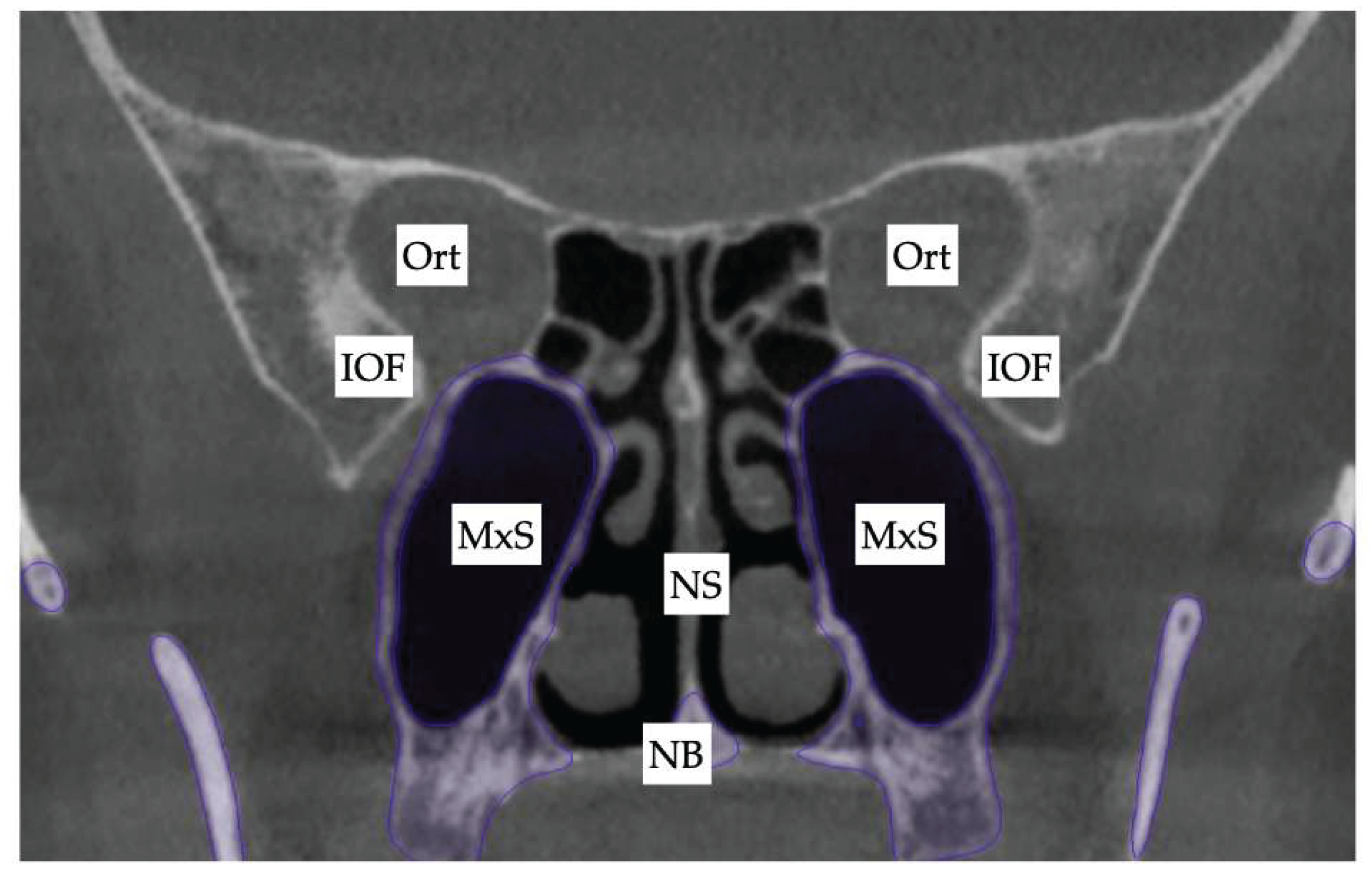
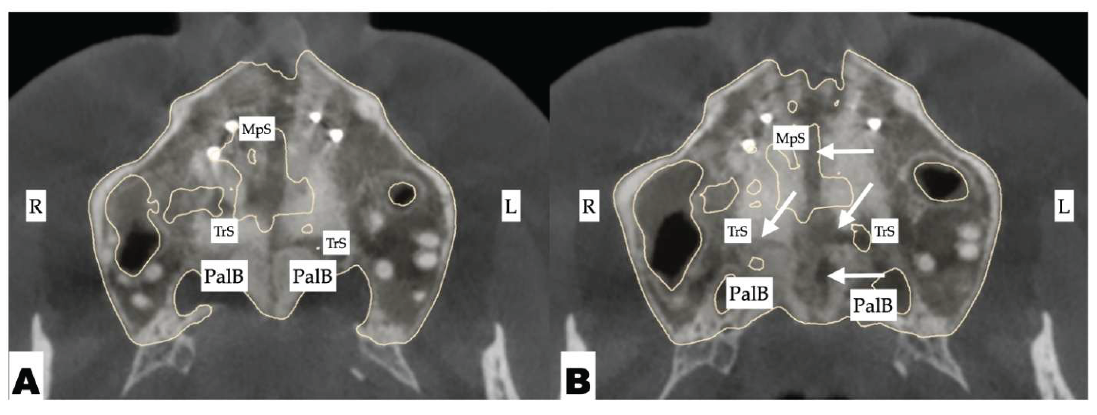
Figure 2. Disarticulation of the midpalatal suture following 3D-guided midpalatal piezocorticotomy and MARPE expansion. A—Pre-expansion view of the midpalatal suture and the respective attachment of the nasal septum. B—Disarticulated view of the midpalatal suture extending from the ANS point (8.79 mm separation) through the middle third of the midpalatal suture (8.47 mm separation) to the PNS region (8.18 mm separation).
Preprints 175625 g002
Figure 3. A. The pre-separation orientation of the pterygomaxillary suture with an angle of 61.78 degrees between the left pterygomaxillary suture and the midpalatal suture. B. The final disarticulation of the left pterygomaxillary, amounting to 0.77 mm. C. The final disarticulation of the right pterygomaxillary suture, amounting to 0.52 mm in the axial plane.
Preprints 175625 g003
Figure 4. The length and orientation of the pterygomaxillary suture in the sagittal plane before disarticulation. A. Left pterygomaxillary suture length 10.80 mm. B. Right pterygomaxillary suture length 13.46 mm.
Preprints 175625 g004
Figure 5. The disarticulation of the pterygomaxillary suture in the sagittal plane. A. Left pterygomaxillary suture length disarticulation, 1.23 mm. B. Right pterygomaxillary suture disarticulation, 1.06 mm.
Preprints 175625 g005
Figure 6. A. The location of the frontonasal suture before 3D-guided midpalatal piezocorticotomy-assisted MARPE separation. B. A frontonasal suture separation of 2.03 mm after 3D-guided midpalatal piezocorticotomy-assisted MARPE separation.
Preprints 175625 g006
Figure 7. Zygomaticomaxillary suture before 3D-guided midpalatal piezocorticotomy MARPE expansion. A. Before expansion. B. After expansion. No distinct disarticulation is visible in previously articulated locations.
Preprints 175625 g007
Figure 8. Frontozygomatic suture changes with 3D-guided midpalatal piezocorticotomy-assisted MARPE expansion. A. Before expansion. B. After expansion. No noticeable changes noted in coronal plane.
Preprints 175625 g008
Figure 9. The nasolacrimal canal composed of the anterior wall of the lacrimal process of the maxillary bone and the lacrimal bone posteriorly. The lacrimomaxillary suture is shown with the straight white arrow. A. Before 3D-guided midpalatal piezocorticotomy MARPE expansion. B. After 3D-guided midpalatal piezocorticotomy MARPE expansion. No separation of the lacrimomaxillary suture is noted.
Preprints 175625 g009
Figure 10. Superimposition of the skull base with the facial skeleton, with skeletal meshes rendered in NemoFab software (Nemotec, Madrid, Spain): beige mesh—before expansion; blue mesh—after 3D-guided midpalatal piezocorticotomy MARPE expansion. A. The resulting vector of expansion, showing minimal changes in the frontal bone position, including glabella, with parallel and even disarticulation of both sides following the initial arrangement of the perimaxillary structures. B. A midsagittal slice of the sphenoid sinus with the superimposed anterior base of the skull, frontal sinus, frontal bone, and Sella region.
Preprints 175625 g010
Figure 11. Superimposition of the skull before and after 3D-guided midpalatal piezocorticotomy MARPE expansion over the sphenoid sinus (NemoFab software, Nemotec, Madrid, Spain). A. Superimposition of the maxillary sinuses: RMS—Right Maxillary Sinus; LMS—Left Maxillary Sinus. Pre-expansion width of the RMS at the level of the median nasal meatus, 10.91 mm; post-expansion width at the same level, 15.05 mm; pre-expansion width of the RMS at the level of the inferior nasal meatus, 13,09 mm; post-expansion width, 12,66 mm; pre- and post-expansion width of the LMS, 16.15 mm; pre-expansion width of the LMS, 13.42 mm; post-expansion width, 13.64 mm. B. Post-expansion changes in the pterygoid plate orientation: SphS—sphenoid sinus; LPt—lateral pterygoid plate; MPt—medial pterygoid plate.
Preprints 175625 g011
Figure 12. Case 2. The initial inclination (yaw) of the maxillary base at the level of the posterior wall of the maxillary sinuses and the inferior orbital fissure. Ort—Orbit; IOF—Inferior Orbital Fissure; MxS—Maxillary Sinus; NS—Nasal Septum; NB—Nasal Base.
Preprints 175625 g012
Figure 13. Case 2. Axial slices of the maxillary dental arch at different levels of the root length. A—Axial slice at the level of the apical third of the root length. B—Axial slice at the level of the middle third of the maxillary tooth root lengths. C—Axial slice at the coronal third of the root lengths. D—Axial slice at the crown level of the maxillary teeth. MpS—Midpalatal suture; Imp—Dental Implant. Asymmetric positions of the first maxillary molars are evident in axial slices.
Preprints 175625 g013
Figure 14. The sagittal view of the axial cross-section of maxillary incisors: A—Maxillary right lateral incisor; B—maxillary right central incisor; C—maxillary left central incisor; D—maxillary left lateral incisor. The axial inclination of the maxillary left incisors is steeper compared to the right side.
Preprints 175625 g014
Figure 15. Case 2. Process of 3D-guided midpalatal piezocorticotomy-assisted MARPE expansion. A, D—Pre-expansion occlusal and frontal views; B, E—4 weeks of expansion after 3D-guided midpalatal piezocorticotomy-assisted MARPE expansion, activation 1 turn/day (0.11 mm/turn); C, F—post-expansion progress prior to initiation of aligner space closure and alignment.
Preprints 175625 g015
Figure 16. Case 2. Disarticulation of the midpalatal and transverse sutures with 3D-guided midpalatal piezocorticotomy-assisted MARPE expansion. Both axial slices show the disarticulation of the transverse suture with a greater degree of separation on the left side. Arrows point to areas of disarticulation. R—Right side; L—left side; MpS—midpalatal suture; TrS—transverse suture; PalB—palatine bone.
Preprints 175625 g016
Figure 17. The progression of post-expansion aligner dentoalveolar movements with redistribution of teeth along the dentoalveolar process for further restorative treatment for microdontia. A—Pre-expansion; B—immediately after completion of 3D-guided midpalatal piezocorticotomy-assisted MARPE expansion; C—distalization of the left posterior teeth initiated with space opening for restorative treatment of lateral incisors and second maxillary left premolar; D-F—progression of direct aligner-assisted tooth movements for premolar de-rotation, molar distalization, and axial inclination correction for maxillary incisors with alignment of incisal edges due to complex root torque movements.
Preprints 175625 g017
Figure 18. The sagittal view of the axial cross-section of maxillary incisors after aligner axis correction: A—maxillary right lateral incisor; B—maxillary right central incisor; C—maxillary left central incisor; D—maxillary left lateral incisor. The axial inclination of all maxillary incisors has improved, with a significant reduction in buccal root torque of the maxillary left central and lateral incisors with directly printed aligner orthodontic movements.
Preprints 175625 g018
Figure 19. Directly printed aligners (Thera-Harz, TA-28 resin, Graphy, Seoul, Korea) in post-expansion stage.
Preprints 175625 g019
Table 1.
Suture nomenclature Associated anatomical structure Paired/Single
Midpalatal Hard palate Single
Palatinomaxillary Hard palate Paired
Nasomaxillary Bridge of the nose Paired
Zygomaticomaxillary Zygomatic arch Paired
Lacrimomaxillary Floor of the Orbit Paired
Ethmoidomaxillary Floor of the Orbit Paired
Sphenomaxillary Floor of the Orbit Paired
Vomeromaxillary Nasal septum Paired
Frontomaxillary Bridge of the nose Paired
Pterygomaxillary Maxillary sinus wall Paired
Table 2. Perimaxillary suture disarticulation amounts following 8.48 mm of midpalatal suture separation with 3D-guided midpalatal piezocorticotomy-assisted MARPE expansion. No changes occurred in the orbital floor or the peri-orbital sutures.
Suture nomenclature Amount of disarticulation
Midpalatal 8.48 mm
Palatinomaxillary (transverse) none
Nasomaxillary 1-2 mm
Zygomaticomaxillary none
Lacrimomaxillary none
Ethmoidomaxillary none
Sphenomaxillary none
Vomeromaxillary 1-2 mm
Frontomaxillary 2.5 mm
Pterygomaxillary 1.06-1.23 mm
Frontonasal 2.03 mm
Frontozygomatic None
Disclaimer/Publisher’s Note: The statements, opinions and data contained in all publications are solely those of the individual author(s) and contributor(s) and not of MDPI and/or the editor(s). MDPI and/or the editor(s) disclaim responsibility for any injury to people or property resulting from any ideas, methods, instructions or products referred to in the content.
Copyright: This open access article is published under a Creative Commons CC BY 4.0 license, which permit the free download, distribution, and reuse, provided that the author and preprint are cited in any reuse.
Prerpints.org logo

Preprints.org is a free preprint server supported by MDPI in Basel, Switzerland.

Subscribe

Disclaimer

Terms of Use

Privacy Policy

Privacy Settings

© 2025 MDPI (Basel, Switzerland) unless otherwise stated