Submitted:
08 April 2025
Posted:
08 April 2025
You are already at the latest version
Abstract
This study presents necessary conditions for the existence and sufficient conditions for the stability or instability of the static meniscus (liquid bridge) appearing in the ribbon single crystal growth from the melt, of predetermined sizes, by using the edge-defined-film- fed (EFG) growth method. The cases when the contact angle and the growth angle verify the inequality 0<αc<π2 -αg or π2>αc>π2 -αg are treated separately. Experimentally, only static meniscus (liquid bridges) which verifies the necessary condition of existence and the sufficient conditions of stability can be created; static meniscus (liquid bridges) which does not verify both of these conditions, exist only in theory because in reality they collapses. The results of this study is significant for thin ribbon single crystal growth from melt, with prior given macroscopic dimensions, using prior given specific equipment. That is because the obtained inequalities represent limits for what can and cannot be achieved experimentally.
Keywords:
static stability
; meniscus
; ribbon growth
; edge-defined-film-fed-growth
MSC: 34B15
1. Introduction
The basic growth methods available for crystal growth are broadly; growth from the melt, growth from vapor, and growth from solution. Modern engineering does not only need single crystals of arbitrary shapes but also plates-, rod-,and tube-shaped single crystals, i.e., single crystals of shapes that allow one to use them as final products without additional machining. This problem appears to be solved by profiled- container crystallization as in the case of casting. However, this solution is not always acceptable. Container material needs to satisfy a certain set of requirements: should be neither react with the melt nor be wetted by it, it should be of high-temperature and aggressive-medium resistant, etc. Even if all these requirements are satisfied perfect –single crystal growth is not secured and growing very thin plate-shaped single crystals, to say nothing of shapes that are more complicated, excludes container application completely. The Springer Handbook of Crystal Growth [1] present on 1816 pages the state of the art in crystal growth until the years 2010. In Chapter 40 pg. 1379-1402 of this book the authors Th. George, St. Balint, L. Braescu presents several mathematical models describing processes, which take place in case of crystal growth from the melt by Bridgman-Stockbarger (BC) and by Edge-Defined-Film-Fed –Growth (EFG) method. For BC growth of cylindrical bar see Figure 1 for ribbon (thin plate) growth by EFG method see Figure 2 and Figure 3.
In case of the BS method, the melt is encapsulated in a crucible and the crystallization of the melt takes place in conditions of permanent contact between the melt and the crystal with the inner wall of the crucible.
A significant advantage of the EFG method in comparison with respect to the BS method is that the crystal is grown without interaction with the crucible, which considerably improves the structural quality of the material: less residual stresses, dislocations, spurious nucleation or twins. In case of EFG method, there is a liquid bridge between the crystal and the shaper (die), called meniscus. The melt is in a crucible, from which it flows through a capillary tube onto the surface of the shaper Figure 2 and Figure 3. Hear a liquid bridge is formed between the shaper surface and the crystal. The crystallization takes place on the so “called crystallization front” which is the border line between the upper part of the liquid bridge and the bottom of the crystal. In the second section of this paper a short mathematical description of the real problem is given. Along with the equations, boundary conditions, and initial values defining the model are presented. In the third section in the framework of the mathematical model, predictions are made concerning the stability and instability of convex meniscus. In the fourth section in the framework of the same mathematical model, predictions are made concerning the stability and instability of concave meniscus. These predictions are made analyzing the static stability or instability of meniscus with theoretical tools presented in [2]. In the fifth section, we discuss the problem what is wanted and wat can be done.
2. Mathematical Description of Meniscus Free Surface
The free surface of the static meniscus, in single crystal growth by EFG method, in hydrostatic approximation is described by the Young- Laplace capillary equation [3,4]:
Here: is the melt surface tension; denote the main normal curvatures of the free surface at an arbitrary point M of the meniscus ; is the pressure above the free surface, equal to the pressure of the gas flow introduced in the furnace for release the heat and thereafter is denoted by .The pressure under the free surface is the sum of the pressure hydrodynamic pressure in the meniscus melt and the hydrostatic pressure of the melt column equal to (see Figure 2 and Figure 3). Here: denotes the melt density; is the gravity acceleration; is the coordinate of M with respect to the Oz axis, directed vertically upwards; denotes the melt column height between the horizontal crucible melt level and the shaper top level. is positive when the crucible melt level is under the shaper top level and it is negative when the shaper top level is under the crucible melt level.
The pressure difference across the free surface is where =. In hydrodynamic equilibrium and =. This pressure difference is constant and it is called the controllable part of the pressure difference . In hydrostatic approximation the Young -Laplace capillary surface equation can be written as:
To calculate the meniscus surface shape and size in hydrostatic approximation is convenient to employ the Young–Laplace Equation (2.2) in its differential form:
For an Oyz plan symmetric meniscus Equation (2.4) become
where :is the single crystal ribbon half-thickness and is the shaper half-thickness.
Equation (2.5) is the Euler equation for the free energy functional of the melt column
The Euler equation is the first order necessary condition of minimum of functional (2.6) namely:
As the Young- Laplace equation in hydrostatic approximation (2.5) is a second order differential equation formulation of the boundary value conditions requires assignment of two boundary conditions; one of the melt crystal interface, the second one on the melt and shaper interface.
The solution of the Equation (2.5) satisfy the following boundary conditions:
where is the growth angle, is the contact angle between the meniscus free surface and the edge of the shaper top.
3. Stability or Instability of a Convex Meniscus
A meniscus is convex if
Remark first that in case of a convex meniscus the function is increasing. This means that the angle between the tangent line to meniscus in every point , and the OX axis is decreasing. In particular, it follows that .Since and we obtain inequality >0 (see Figure 2).
It should be noted that, the convex meniscus stability (the static one) is different from the dynamic stability of the crystallization process. For statically stable convex meniscus, not only necessary first order but also second order sufficient conditions of functional (2.6) should be satisfied. These second order sufficient conditions for the minimum of functional (2.6) are the Legendre condition and the Jacobi condition [5].
The Legendre condition is
Computing we find . Therefore the Legendre condition is satisfied.
The Jacoby condition concern the so-called Jacoby equation:
for which a Sturm type upper bound has to be find [5].
In case of the functional (2.6) Equation (3.2) become:
Remark that for the coefficients of (3.3) the following inequalities hold:
Hence
is a Sturm –type upper bound for (3.3)
Since every non zero solution of the equation vanishes at most once on the interval the solution of the initial value problem
has only one zero on the interval . Hence the stability condition of Jacobi is verified.
This result can be surprising and create the impression that a convex meniscus is stable. In fact, the result is that if a convex meniscus exist, then it is stable. For this reason in the following, we will establish necessary conditions for the existence of convex meniscus (see Figure 2).
Starting from Equations (2.3) and (2.5) it is easy to see that in hydrostatic approximation the pressure difference verify equalities:
Using , the boundary conditions ,, with the Lagrange mean value theorem we obtain that there exists in the interval such that
Since is strictly decreasing on the interval the following inequalities hold
Using equality (3.8) and inequalities (3.9)–(3.11) in hydrostatic approximation, in case of the existence of convex static meniscus, for the pressure difference the following inequalities hold
Therefore in case of convex meniscus the values of the pressure difference has to be researched in the interval where :
For
convex meniscus like in Figure 2 does not exit. These regions of the pressure difference are regions of static instability. A meniscus obtained with in this region collapse. For satisfying one of the inequalities (3.14) it is impossible to create experimentally a convex meniscus like in Figure 2.
Retain that the pressure difference can be controlled by the gas pressure and the parameter .
In the following we will illustrate first the existence of convex static meniscus in case of Germanium (Ge) assuming that
In case of Ge [Pa] and [Pa] and a convex meniscus is obtained for . This meniscus is obtained by integrating the initial value problem:
The numerical values of are:, , , [ ] ,=[rad], The pressure difference was found by trial solving (3.15) for different values of in the range .
The obtained results concerning the meniscus shape and the variation of are presented in the next figures:
Figure 4.
Ge convex meniscus shape for
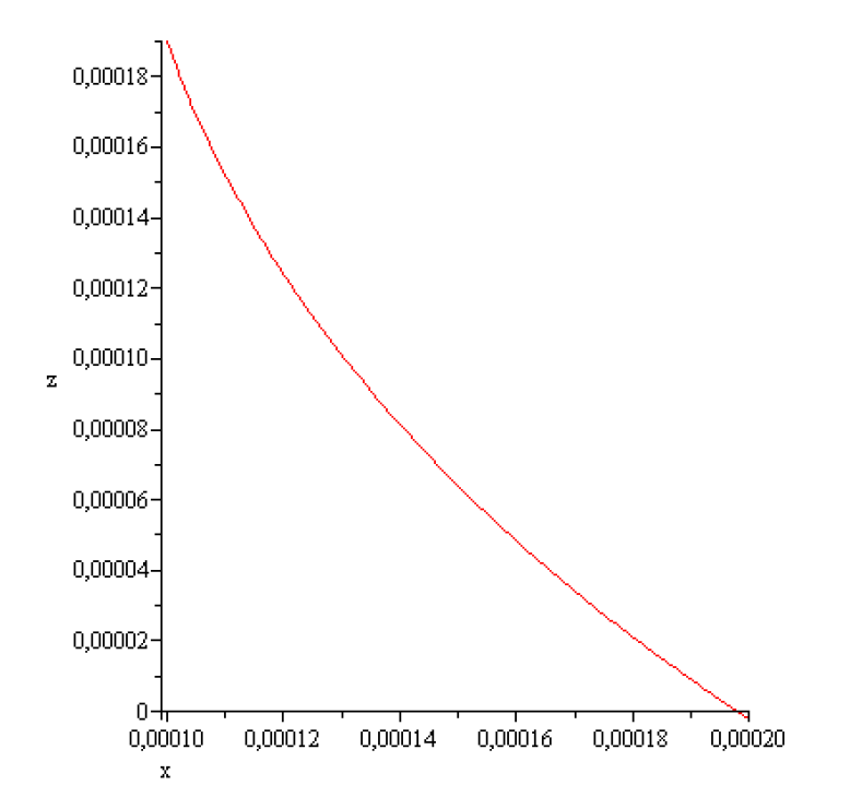
Figure 5.
.  ,
, 
,
According to the above results concerning stability of the static meniscus that of obtained here numerically is stable. It can be realized experimentally!
We continue analyzing what happens numerically if or .
This computation shows that for the meniscus shape is not convex. The purpose to create a convex meniscus, as in Figure 2 is not realizable experimentally!
This computation shows that for the meniscus shape is not convex. The purpose to create a convex meniscus, as in Figure 2 is not realizable experimentally!
Remember that in hydrostatic approximation . This relation can be used for the control of via and .
For example if then and for a given gas pressure we can find , namely . For instance if we have = 0.02411897481[m]. This means that the crucible melt level has to be under the shaper top level with 0.02411897481[m].
If and then . This means that the crucible melt level is under the shaper top level with [m].
If and then [m]. This means that the shaper top level is under the crucible melt level with .
3. Stability or Instability of Concave Meniscus
A meniscus is concave if
Remark that in case of a concave meniscus the function is decreasing. Therefore, the angle between the tangent line to meniscus in every point, and the OX axis is increasing. In particular, it follows that. Since and we obtain inequality . (see Figure 3).
It should be noted that, the concave meniscus stability (the static one) should be distinguished from the dynamic stability of the crystallization process. For statically stable concave meniscus, not only necessary first order but also second order sufficient conditions for the minimum of functional (2.6) should be satisfied. These second order sufficient conditions for the minimum of functional (2.6) are the Legendre condition and the Jacobi condition [5]. Since the functional is the same as in convex meniscus case the Legendre condition and the Jacobi condition are the same as in the case of convex meniscus i.e.,
Only the evaluation of coefficients of the Equation (4.2) change, and in concave case is given by:
Hence
is a Sturm –type upper bound for (4.2).
Since every non zero solution of the equation vanishes at most once on the interval the solution of the initial value problem
has only one zero on the interval . Hence the stability condition of Jacobi is verified.
This result can create the impression that a convex meniscus is stable. In fact, the result is that if a concave meniscus exist, then it is stable. For this reason in the following, we will establish necessary conditions for the existence of concave meniscus (see Figure 3).
Starting from Equations (2.3) and (2.5) it is easy to see that in hydrostatic approximation the pressure difference verify equalities:
Using , the boundary conditions ,, with the Lagrange mean value theorem we obtain that there exists in the interval such that
Since is strictly increasing on the interval the following inequalities hold:
Using equality (4.7) and inequalities (4.8)–(4.10) in hydrostatic approximation, in case of the existence of concave static meniscus, for the pressure difference the following inequalities hold:
Therefore in case of concave meniscus the values of the pressure difference has to be researched in the interval where:
concave meniscus like in Figure 3 does not exit. These regions of the pressure difference are regions of static instability. A meniscus obtained with in this region collapse. For satisfying one of the inequalities (4.13) it is impossible to create experimentally a concave meniscus like in Figure 3.
The pressure difference can be controlled by the gas pressure and the parameter .
In the following we will illustrate first, the existence of concave static meniscus in case of Germanium assuming that and .This value of can be realized by choosing an appropriate material for shaper.
In case of Ge. . It turns that integrating the initial value problem :
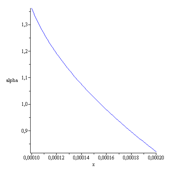
for A typical solution of (4.14) for is represented in the next figures,
The computed figures show that none of the conditions =0[m], is fulfilled.
Therefore for with the prior giving data a concave meniscus like on Figure 3 can not be created. Since for and concave meniscus like in Figure 3 does not exist (see (4.13) it follows that for the above prior given data concave meniscus can not be created experimentally.
In the same time Figure 10 and Figure 11 suggest that increasing the level of the crystallization front creation of a concave meniscus like in Figure 3 wood be possible. In order to verify the true value of this impression we assume that and we compute the corresponding range [, we find [,[-69.613111,159.016207][Pa].This range is larger than that obtained for . Integrating the initial value problem :
for [-69.613111,159.016207]Pa] the following result is found: there exist a concave meniscus for .
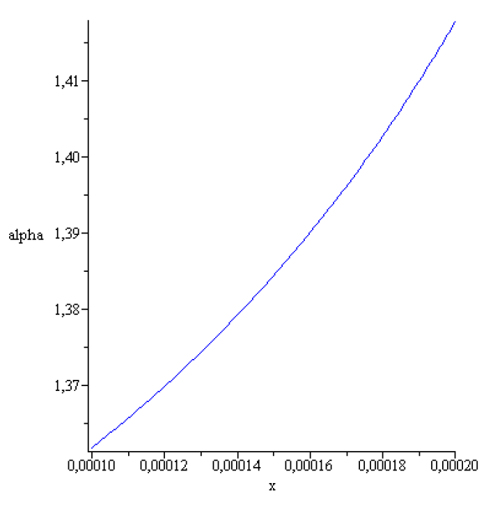
The meniscus and the angle are represented in the next figures:
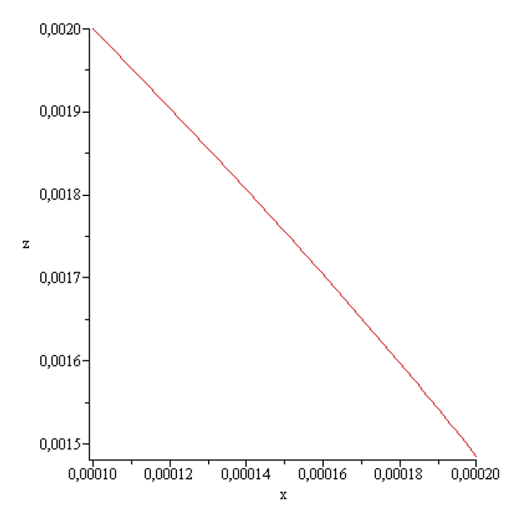
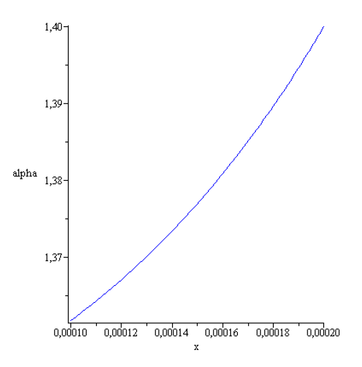
Figure 12.
for
Figure 13.
for
This meniscus exist, it is stable and can be created experimentally.
For and concave static meniscus does not exit. Therefore can not be created experimentally.
A meniscus and obtained for are presented in the next figures:
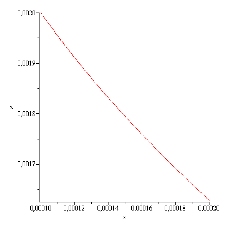
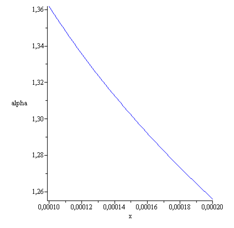
Figure 14.
for
Figure 15.
for
A meniscus shape and obtained for and are represented in the next figures:
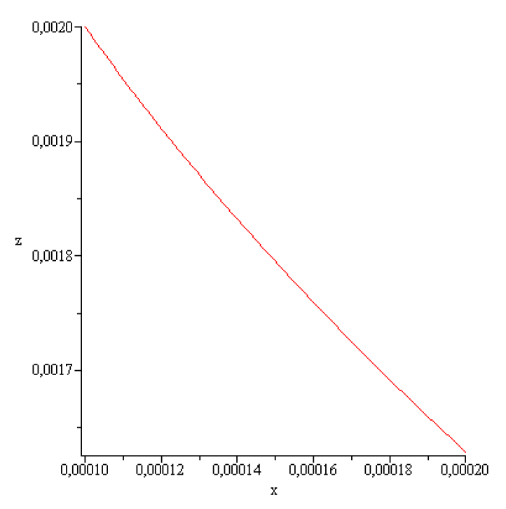
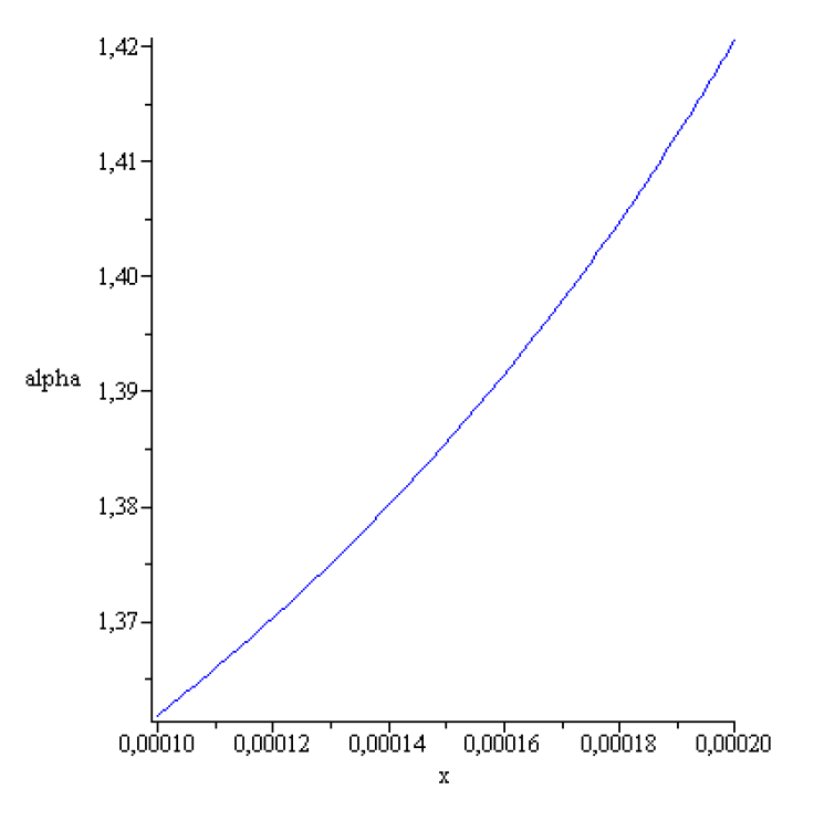
Figure 16.
for
Figure 17.
for
Note that experimentally the increase of the crystallization front from to imply modification of the thermal field.
Remember that in hydrostatic approximation . This relation can be used for the control of via and .
For example if then and for a given gas pressure we can find , namely . For instance if we have = 0.0007463229940[m].This means that the crucible melt level is under the shaper top level with 0.0007463229940[m].
If and then −0.00493301295[m]. This means that the shaper top level is under the crucible
melt level with −0.00493301295[m].
If and then [m].
This means that the shaper top level is under the
crucible melt level with −0.000709916994[m].
5. Results
Necessary conditions for the existence and sufficient conditions for the stability or instability of the static meniscus (liquid bridge) appearing in the ribbon single crystal growth from the melt, of predetermined sizes, by using the edge-defined-film- fed (EFG) growth method, are presented. Theoretical results are illustrated numerically in case of Germanium ribbon growth.
6. Comments and Conclusions
The main novelty in this article consists in the obtained inequalities. These represent limits for what can and cannot be achieved. Experimentally, only stable static liquid bridges can be created if they exist theoretically. Unstable static liquid bridges could exist just in theory; in reality, they collapse; therefore, they are not appropriate for crystal growth.
Author Contributions
The authors contributed equally to the realization of this work. All authors have read and agreed to the published version of the manuscript.
Funding
This research did not receive any specific grant from founding agencies in the public, commercial or not-for-profit sectors.
Data Availability Statement
The original contributions presented in the study are included in the article; further inquiries can be directed to the corresponding author.
Conflicts of Interest
The authors declare no conflicts of interest.
References
- Springer Handbook of Crystal Growth; ISBN:978-3-540-74761-1. [CrossRef]
- Cojocaru, A.V.; Balint, S. Stability or Instability of a Static Liquid Bridge Appearing in Shaped Crystal Growth from Melt via the Pulling-Down Method. Fluids 2024, 9,176. [CrossRef]
- R. Finn, Equilibrium Capillary Surfaces, vol. 284 of Grundlehren der Mathematischen Wissenschaften, Springer, New York, NY, USA, 1986.
- V. A. Tatarchenko Shaped Crystal Growth, Kluwer Academic Publishers, Dordrecht, The Netherlands, 1993.
- P.Hartman, Ordinary Differential Equations, John Wiley & Sons, New York, NY, USA, 1964.
- S.Balint,A.M.Balint,R Szabo; Nonlinear boundary value problem for concave capillary surfaces occurring in single crystal ribbon growth from the melt, Nonlinear Studies Nonlinear Studies Vol. 17, No. 1, pp. 65-76, 2010.
- S. Balint and A. M. Balint. Nonlinear Boundary Value Problem for Concave Capillary Surfaces Occurring in Single Crystal Rod Growth from the Melt. Hindawi Publishing Corporation, Volume 2008, Article ID 310924, 13 pages. [CrossRef]
Figure 1.
Cylindrical bar BC growth.
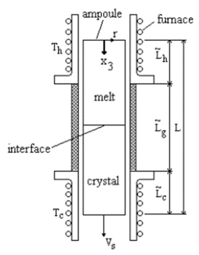
Figure 2.
Ribbon growth,
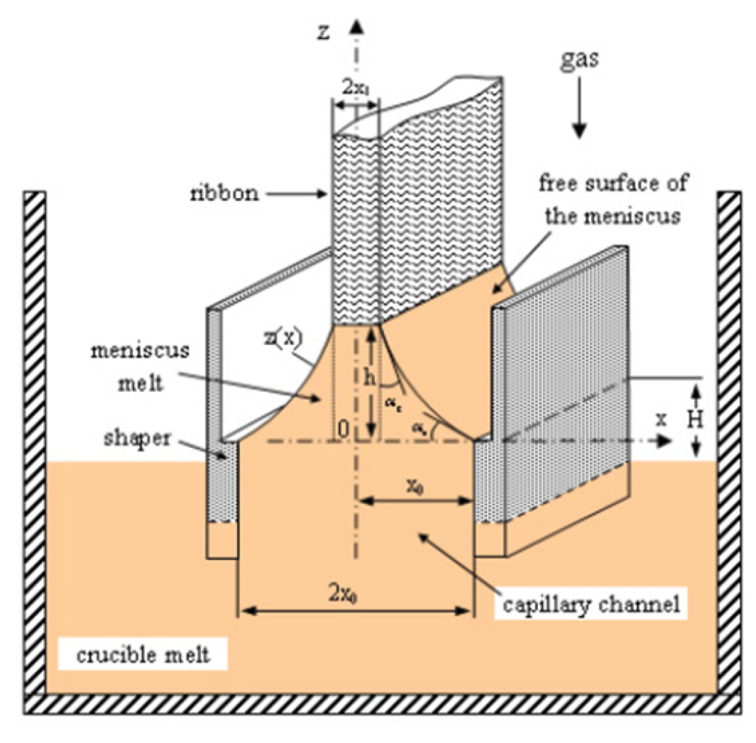
Figure 3.
Ribbon growth, >
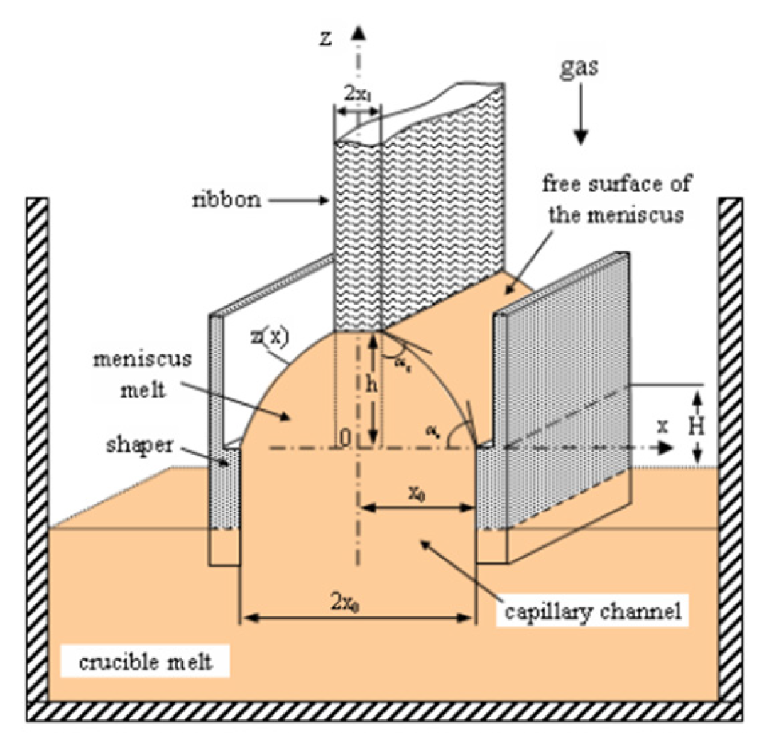
Figure 6.
Ge meniscus shape for
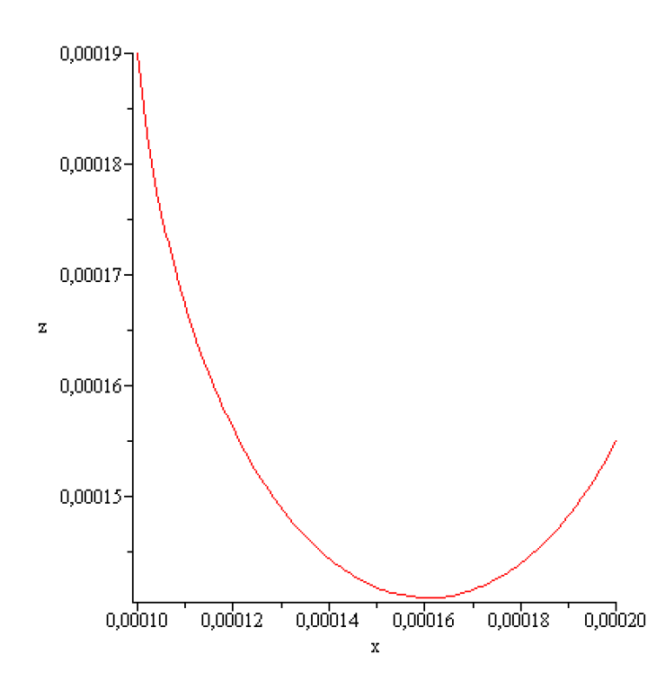
Figure 7.
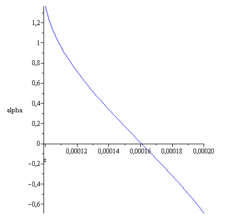
Figure 8.
Ge meniscus shape for
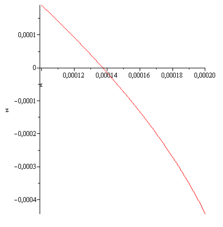
Figure 9.
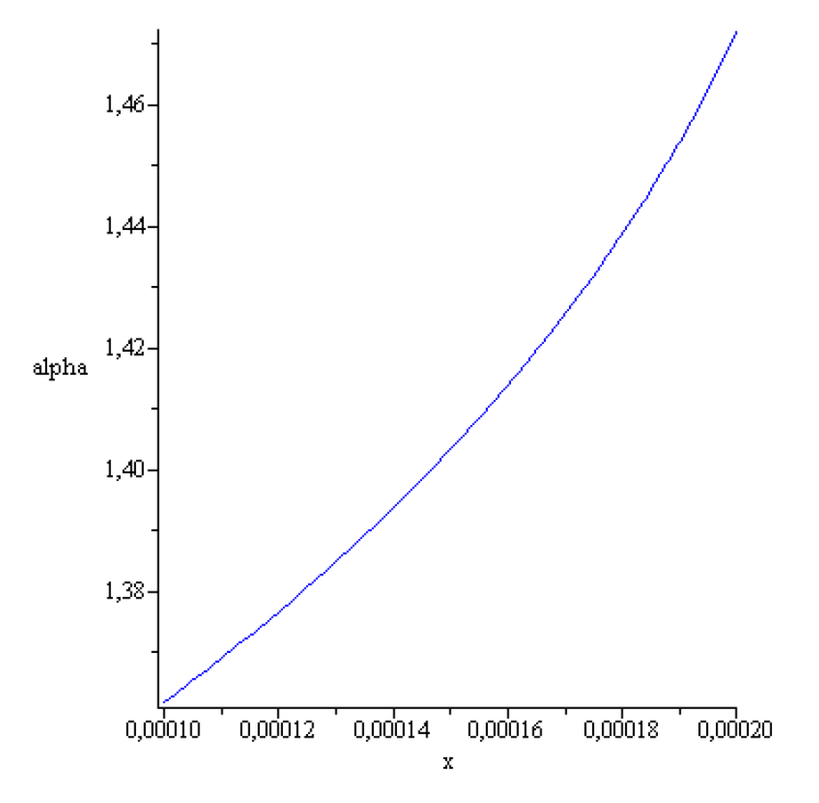
Figure 10.
for
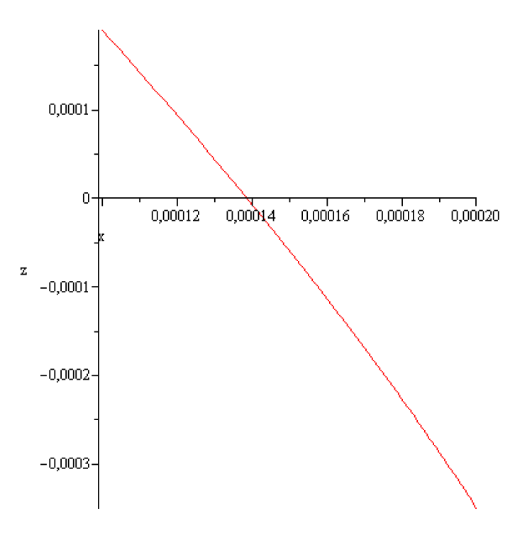
Figure 11.
versus
Disclaimer/Publisher’s Note: The statements, opinions and data contained in all publications are solely those of the individual author(s) and contributor(s) and not of MDPI and/or the editor(s). MDPI and/or the editor(s) disclaim responsibility for any injury to people or property resulting from any ideas, methods, instructions or products referred to in the content. |
© 2025 by the authors. Licensee MDPI, Basel, Switzerland. This article is an open access article distributed under the terms and conditions of the Creative Commons Attribution (CC BY) license (http://creativecommons.org/licenses/by/4.0/).
Copyright: This open access article is published under a Creative Commons CC BY 4.0 license, which permit the free download, distribution, and reuse, provided that the author and preprint are cited in any reuse.


