
Submitted:
24 March 2025
Posted:
24 March 2025
You are already at the latest version
Abstract
A new Common-Mode (CM) choke with asymmetrical winding capable of attenuating Differential-Mode (DM) and Common-Mode (CM) noise for AC to DC Power Converters is proposed in this paper. For a conventional CM choke with symmetrical winding, the CM and DM noise are also attenuated by the magnetizing inductance (LM) and very small leakage inductance (Lk) due to the higher coupling factor, respectively, of the CM choke. However, because the number of turns is limited according to the shape and size of the CM choke, it is very difficult to find the proper leakage inductance (Lk) to eliminate the DM noise thoroughly. For this reason, a bulky CM choke is required for a larger leakage inductance (Lk). Typically, another DM choke is used, for the sole purpose of DM noise attenuation. Therefore, the cost and size of the EMI filters for use with a conventional CM choke can increase. To solve these problems, the proposed CM choke with asymmetrical winding is introduced in this paper. Different from the conventional CM choke with symmetrical winding, the magnetizing inductance (LM) of the proposed CM choke with asymmetrical winding can suppress not only CM but also DM noise. Therefore, the proposed CM choke with asymmetrical winding can effectively attenuate CM and DM types of noise even with fewer and smaller turns. This method can be applied to all types of power converters which use two- or three-stage systems. To confirm the validity and superiority of the proposed CM choke, comparisons of the total noise as well as the DM and CM noise characteristics between conventional and proposed CM chokes are presented in this paper. Lastly, a practical approach to the design of an EMI filter and the design procedures are also presented and addressed.
Keywords:
EMI filter
; conducted EMI
; asymmetrical winding CM choke
; CM noise attenuation
; DM noise attenuation
1. Introduction
Recently, most power conversion systems use a SMPS (Switching Mode Power Supply) satisfying requirements for high efficiency, high power density and high reliability. The high-frequency switching operation of these systems becomes the main source of the high-frequency conducted EMI (Electro-Magnetic Interference) noise due to the fast switching currents di/dt and voltages dv/dt. Therefore, EMI filters have been widely used to suppress the high frequency conducted EMI noise for power electronic applications for many years [1,2,3,4,5]. Because EMI noise can affect other power electronic systems connected to the same line, a CISPR, an organization affiliated with the IEC (International Electrical Committee), establishes noise limits at certain levels. The CISPR limits concern conducted and radiated emissions of devices, where the conducted emissions are caused by the currents passing through the unit’s AC power cord [6]. For this reason, EMI filters have long been largely used for AC to DC converter, DC to DC converter and etc. especially in power electronic areas to attenuate the switching noise and meet the EMI standards. EMI noise is traditionally categorized as Differential Mode (DM below) and Common Mode (CM below) current especially in AC to DC power converter system with Flyback DC to DC converter, as shown in Figure 1.
While DM noise is caused by the noise current flowing within the power delivery path, CM noise is caused by the noise current flowing between the chassis ground and the power circuit [7]. To suppress these types of noise, CM and DM chokes are required. Generally, a CM choke includes a very small leakage inductance (), as well as a large magnetizing inductance () since the coupling coefficient () is tightly coupled to less than 1.0, where the magnetizing inductance () and leakage inductance () serve respectively as CM and DM chokes. However, if the level of DM noise is high at a frequency range lower than 1MHz, a very small leakage inductance () cannot attenuate it to a suitable level. Therefore, several serially connected CM chokes, a CM choke with a greater number of turns for a large leakage inductance (), or an additional large DM choke have been used. However, these conventional methods not only increase the filter size and cost of production but also deteriorate the power conversion efficiency. To overcome these drawbacks, a new CM choke with asymmetrical winding is proposed in this paper. The main concept of the proposed CM choke with asymmetrical winding is that it uses not only the leakage inductance () but also the magnetizing inductance () to attenuate CM and DM noise at the same time. The proposed method can simplify the construction of the EMI filter without additional components. To verify the feasibility and superiority of the proposed CM choke with asymmetrical winding, a comparison is done of the overall, the DM, and the CM noise characteristics between the conventional and the proposed CM choke with asymmetrical winding. Lastly, a practical approach to the design of an EMI filter is also presented and addressed.
2. CM and DM Noise Modeling of the Proposed CM Choke with Asymmetrical Winding
Given that the characteristics of CM and DM types of noise differ, the parasitic elements related to CM noise also differ from those of DM noise. The CM and DM noise modeling of a conventional CM choke can be represented as shown in Figure 2(a,b). The two windings ( and ) that have the same number of turns on the primary and secondary windings () serve as the conventional CM choke windings, where is the number of turns on the primary side, and is the number of turns on the secondary side of a conventional CM choke. The equivalent CM and DM impedances of a conventional CM choke are used to estimate the CM and DM noise modeling. The formal equations can be generally expressed as the following Equations (1) and (2) to analyze the equivalent CM and DM impedances of a conventional CM choke [8,9,10].
where and are the corresponding voltage of and CM noise current, respectively, in Figure 2(a). and are also the corresponding voltage of and DM noise current, respectively, in Figure 2(b). are the mutual inductance between the primary and secondary windings. The mutual inductances of the primary and secondary windings to the secondary and primary windings are defined as and , respectively, which are the same values, so . and currents in the live and neutral lines have theoretically the same magnitude when considering only CM noise currents, so . and currents in the live and neutral lines have theoretical currents flowing in the opposite direction but have the same magnitude when considering only DM noise currents, so . As shown in Figure 2(b), according to Kirchhoff’s voltage law and current law, voltage can be expressed as the sum of and voltages. For simplicity, the mutual inductance between the primary and secondary windings can be determined by the transformer’s theory. This is because the primary and secondary windings are wound on the same toroidal core and are perfectly coupled together, so the coupling coefficient () is equal to 1.0. In other words, when the inductances of the two windings are the same values and equal, is equal to , the mutual inductance that exists between the two windings will equal the value of one single winding as the square root of two equal values is the same as one single value as shown in the following Equation (3).
where, as described above, if is equal to , , which is the mutual inductance between two windings, can be expressed as based on Equation (3).
Using Equations (1)–(3), the equivalent CM and DM impedances ( and ) of a conventional CM choke can be written as the following Equations (4) and (5), respectively.
where, and are the equivalent CM impedances of a conventional CM choke, which are the same values and attenuate CM noise currents, so . and are the equivalent CM impedances of a conventional CM choke, which are the same values, so . However, as shown in Equation (3), since the mutual inductance () is theoretically equal to and , and values become zero, the same values, and cannot attenuate DM noise currents. As stated above, can be expressed as the sum of and since is the sum of and .
Based on Equations (4) and (5), the CM and DM inductances ( and ) involved in the CM and DM impedances of a conventional CM choke can correspondingly be expressed as the following Equations (6) and (7).
As shown in Equations (6) and (7), when the coupling coefficient () is perfectly coupled for this reason, it can be confirmed that a conventional CM choke can only attenuate CM noise.
However, in general, a conventional CM choke includes a very small leakage inductance (), as well as a large magnetizing inductance () since the coupling coefficient () is tightly coupled to less than 1.0, where the magnetizing inductance () and leakage inductance () serve respectively as CM and DM chokes. The equivalent CM and DM impedances of a conventional CM choke, taking into account the magnetizing inductance () and leakage inductance (), are used to estimate the CM and DM noise modeling. The formal equations, including the magnetizing inductance (), the leakage inductance (), and the mutual inductance( and ), can be generally expressed as the following Equations (8) and (9) to analyze the equivalent CM and DM impedances of a conventional CM choke.
where, the self-inductances ( and ) between two windings are composed of the sum of the magnetizing inductances( and ) and the leakage inductances ( and ), respectively. and are the leakage inductances of the self-inductances ( and ), which are the same values, so . The mutual inductances ( and ) of the primary and secondary windings to the secondary and primary windings are determined by the control factors of the coupling coefficients( and ), the number of turns on the primary and secondary windings ( and ), the self-inductances ( and ) and the magnetizing inductances( and ). Therefore, if the coupling coefficient () of two windings is tightly coupled to less than 1, the mutual inductances ( and ) of the primary and secondary windings to the secondary and primary windings can be expressed as the following Equations (10) and (11). As stated above, and currents in the live and neutral lines also have theoretically the same magnitude when considering only CM noise currents, so . and currents in the live and neutral lines have theoretical currents flowing in the opposite direction but have the same magnitude when considering only DM noise currents, so .
where, as shown in Equations (8) and (9), if and are equal to and , and are the mutual inductances of the primary and secondary windings to the secondary and primary windings, which are the same values, so [11,12].
As described above, using Equations (8)–(11), the equivalent CM and DM impedances of a conventional CM choke can be written as the following Equations (12) and (13).
Figure 3 shows the CM and DM noise current flows of a conventional CM choke considering the magnetizing inductance () and the leakage inductance ().
As shown in Figure 3, because CM noise currents in the live and neutral lines flow in the same direction, the magnetizing inductance () of a traditional CM Choke participates in attenuating the CM noise. On the other hand, because the DM noise currents in the live and neutral lines flow in the opposite direction, the leakage inductance () contributes to the attenuation of the DM noise.
Using Equations (12) and (13), the CM and DM inductances ( and ) involved in the CM and DM impedances of a conventional CM choke can correspondingly be expressed as the following Equations (14) and (15).
where, Equations (14) and (15) are the simplified equivalent inductances of the CM and DM inductances ( and ) considering the magnetizing inductance () and the leakage inductance () because the leakage inductance ( of conventional CM choke has much smaller than the magnetizing inductance () of that, the CM inductance () can be approximated as the magnetizing inductance (), as expressed in Equation (14). If the level of DM noise at a frequency lower than the self-resonant frequency (SRF) of the CM choke is too high, the DM inductance (), i.e., the leakage inductance (), is too small to attenuate the DM noise. Therefore, to suppress the DM noise using high magnetizing inductance (), a new CM choke with asymmetrical winding is proposed, in which the turns ratio of a new CM choke’s primary and secondary windings is not equal. This proposed CM choke with asymmetrical winding of a non-identical turns ratio causes the DM current to flow through the magnetizing inductance (). Using Equations (8)–(11), Figure 4 and Figure 5 show the coupled and non-coupled model of the proposed CM choke at the CM and DM noise current flows. By de-coupling the original coupled model of the proposed CM choke and then transforming the dual current sources into the single current source, the CM and DM noise impedances in the live and neutral lines can be derived, as shown in Figure 4 and Figure 5.
Therefore, as shown in Figure 4b and Figure 5b, the CM and DM inductances ( and ) of the proposed CM choke with asymmetrical winding can be derived as the following Equations (16) and (17), respectively, where the leakage inductance ( is assumed to be much smaller than the magnetizing inductance (.
Figure 6 and Figure 7 show the CM and DM impedances calculated using the PSIM simulation tool on the conventional and proposed CM chokes, where the parasitic capacitance and resistance are considered [13,14]. Practically, the parasitic impedances originating from the inter-winding capacitance attenuate effectively the EMI noise, but the amount is negligible at a low frequency. Beyond a certain frequency, the effects of parasitic elements start to surface. This frequency is the dividing line between the “high frequency” and “low frequency” points. The effects of high-frequencies include the permeability reduction of the CM choke core, the parasitic capacitance effect of the inductor, and the parasitic inductance effect of the filter capacitors. Besides these effects of parasitic elements, radiation coupling and source impedance-filter capacitor resonance can also affect the high-frequency EMI performance. These factors also affect the noise passing through the EMI filter [15]. However, these effects are beyond the scope of this paper.
As shown in Figure 6, the CM impedance () of the proposed CM choke with asymmetrical winding is nearly equal to the CM impedance ( of a conventional choke. However, compared to the conventional DM impedance (), the proposed DM impedance () is greater by more than 40 times at low frequencies with the aid of the magnetizing inductance () as shown in Figure 7. Therefore, the proposed CM choke with asymmetrical winding can attenuate the DM noise more effectively compared to a conventional choke. The equivalent DM impedance of proposed CM choke with asymmetrical winding is very low at the second resonant frequency. Subsequently, the DM noise cannot be attenuated. However, the low DM impedance at such frequencies is insignificant because the DM noise is usually insignificant at a high frequency. If the DM noise at these frequencies is high, the proposed CM choke with asymmetrical winding can have a high DM impedance by varying the turns ratio. Specifically, a high turns ratio of the proposed choke can increase the second resonant frequency.
3. Design Considerations of the Proposed CM Choke with Asymmetrical Winding
The noise attenuation of the EMI filter must be analyzed before designing it. However, the noise source and its source impedance can differ according to the PCB pattern, the position of the EMI filter, the types of SMPS, and other factors. Therefore, the noise attenuation capability of the same EMI filter can differ according to SMPS [15]. From the design procedure proposed in earlier work [16], the required CM and DM impedances ( and ) can be obtained from the required CM attenuation (), the required DM attenuation () and the noise source impedances ( and ) as the following Equations (18) and (19).
where, the values of , , and can be determined through measurements and “”and “” denote the equivalent impedances of the LISN [16,17]. Therefore, from Equations (18) and (19), the CM and DM inductances ( and ) can be calculated.
Figure 8 shows a commonly used EMI filter configuration with components and an AC to DC Power Converter System(EMI source). Because the coupling capacitors between the ‘Hot’ and ‘Cold’ ground points act as the Y-capacitors, the Y-capacitors may be placed only near the AC line [18]. Similarly, given that a large input capacitor is used at the input side of the Power Converter, the X-capacitor may be placed only near the AC line.
If the EMI filter consists of only a CM choke without X-capacitor and Y-capacitors, the CM and DM inductances must be large enough to attenuate each respective type of noise. However, because X-capacitor and Y-capacitors are typically used together with a CM choke, the CM and DM inductances can be designed to be smaller than the results determined by Equations (18) and (19), respectively. Therefore, the CM and DM impedances ( and ), considering the existence of X-capacitor and Y-capacitors, can be re-calculated using the following Equations (20) and (21).
where and are the impedances of the X-capacitor and Y-capacitors, respectively. Moreover, because the Y-capacitors are used in live-to-ground and neutral-to-ground configurations, the impedance of the Y-capacitors is divided by 2.
To implement the choke with the CM and DM inductances as calculated by Equations (21) and (22), the number of turns should be determined, considering the core shape, size, material, and -value. The number of primary turns can be derived from the following Equation (23) [19,20,21].
where the -value is the same as permeance and is a measure of inductance in magnetic cores. Equations (16) and (17) can determine the number of turns on the secondary winding. Core saturation should be considered at the end of the design. Because a large amount of DM current does not flow through the magnetizing inductance (, the conventional CM choke is rarely saturated. On the other hand, because the DM current of the proposed CM choke with asymmetrical winding flows through the magnetizing inductance (, the core saturation must be considered. This is done with the following Equation (24).
where,, and represent the permeability of a magnetic core, the peak current flowing through the AC line, and the mean path length of a magnetic core, respectively.
Based on the previous discussion, a flow chart [22,23,24] for designing the proposed CM choke with asymmetrical winding is proposed in Figure 9. As shown in Figure 9, the first step is to measure the CM and DM noise of a conventional CM choke using a noise separator. As expressed in equations (21) and (22), the second step is to determine the required CM attenuation, considering Y-capacitance, and the required DM attenuation, considering X-capacitance, respectively, using the CM and DM noise of a conventional CM choke obtained from the first step. The third step is to calculate the CM and DM inductances based on the data obtained from the second step. The fourth step is to determine the wire size [25,26] based on the nominal area of the wire, which is listed on the wire manufacturer’s data sheets, the winding fill factor, the core window area, the number of turns between two windings, and the peak winding current [25]. The fifth step is to choose a core size that is large enough to fit the turns of the wire gauge and satisfy the core geometrical constant [25]. The sixth step is calculate the number of turns on the primary winding using Equation (23). The seventh step calculates the turns ratio, which is the number of turns between the primary and secondary windings, based on the sixth step. The eighth step is to determine whether the total winding area of the primary and secondary windings is included in the core window area. If the total winding area is not included in the core window area, the design process is repeated from the fifth stage to meet the design condition. The final step is to determine whether the core is saturated using Equation (24). If the core is saturated, the design process is repeated from the fifth step until it meets the design condition.
4. Experimental Results and Discussion
Figure 10 shows the 45W Flyback DC to DC converter implemented in an AC to DC power converter system. The design specifications of input voltage (), input maximum current (), output maximum current () and output voltage () are , , and , respectively. The EMI filter is composed of one X-capacitor (, two Y-capacitors ( and one CM choke. To adhere to the applicable regulation (CISPR 22-class B limit), the CM choke (TNC corporation-CV408360S, 36mH, 69 turns) is used as a conventional filter. The leakage inductance of the conventional CM choke is approximately .
Figure 11 shows the test setup of conducted EMI measurement used to measure the EMI noise in a practical AC to DC power converter system. In Figure 11, the CM and DM noise are measured using a line impedacne stabilizing network(LISN), a noise separator(EMCIS-EA 2100), an attenuator, and an Agilent 4395A spectrum analyzer, where a noise separator can be used to separate the CM and DM noise, and a spectrum analyzer can be used to calculate the CM and DM noise from the other measured result. As shown in Figure 11, an attenuator in EMI equipment is used to reduce the strength of an EMI signal to prevent it from interfering such as the high-frequency surge current generated by the operation of electronic devices.
The measured result, as shown in Figure 12b, indicates that the average DM noise margin of the conventional choke is as low as approximately 5 [dB] at 195 [KHz]. Because the tolerance of the component affects the noise performance, a 10 [dB] margin for mass production is required. Therefore, margin exceeding 5 [dB] must be added considering the DM noise. In order to meet these specifications with a conventional EMI filter, the leakage inductor of the CM choke must be larger or an additional DM inductor must be used. In addition, for a design with higher leakage inductance, a greater number of turns as well as a larger core are required. Fortunately, the CM noise has a sufficient margin at 195 [KHz]; hence, the designed CM inductance can be smaller than that associated with a conventional CM choke. Through Equations (21) and (22), and are derived again for the design of the proposed CM choke with asymmetrical winding. The required CM inductance is and the required DM inductance is . The minimum number of turns of the proposed CM choke with asymmetrical winding can be calculated through the CM inductance. Given an -value of , this number is calculated as 66. With Equation (17), the turns ratio of the proposed CM choke with asymmetrical winding can be derived, with the determined value here being 72:66.
As noted above, the saturation magnetic flux density for the proposed CM choke with asymmetrical winding should be considered. Because the magnetic flux density is proportionate to the number of turns, the input current, and the permeability, the turns ratio is limited to the saturation magnetic flux density. Most manufacturing processes include data related to the maximum magnetic density of the core. With Equation (24), the core cannot be saturated because the maximum magnetic flux density cannot exceed the saturation magnetic flux density. The measurement results compared with the conventional CM choke and the proposed CM choke with asymmetrical winding are shown in Figure 12 and Figure 13. The DM noise is suppressed to 43.5] at 195] on the average measurement. Although the CM noise is slightly increased, the amount is reasonable at a high frequency (up to 1). This is likely due to the parasitic capacitance effect of the CM choke, the permeability reduction effect of the core material for the CM choke, and especially the equivalent CM and DM inductance reduction effect of the proposed CM choke’s non-coupled model, among other factors. However, these effects are beyond the scope of this paper.
5. Conclusions
A new Common-Mode (CM) choke with asymmetrical winding capable of attenuating Differential-Mode (DM) and Common-Mode (CM) noise for AC to DC Power Converters is proposed in this paper. If the levels of CM and DM noise are high at frequencies of less than 1MHz, CM and DM inductors must be used, requiring a larger filter and an increased cost. In order to ensure a satisfactory level of DM noise with a conventional choke, the leakage inductance () of the CM choke must be larger. For a design with greater leakage inductance (), additional turns are needed and a larger core must be used. In order to use the magnetizing inductance () to suppress the DM noise, the proposed CM choke with asymmetrical winding, where the turns ratio of the primary and secondary windings differ, is used in this paper. With the magnetizing inductance (), the DM noise of an AC to DC power converter system is significantly reduced. Although the CM noise is increased slightly, the amount is within a reasonable range (up to 1). The proposed CM choke with asymmetrical winding is experimentally verified as a simple and effective way for reducing the CM and DM noise in an AC to DC power converter system. Based on the experimental results and analysis of the present study, additional research is required and can be done to make this technology more practical. Further works, the winding method of the proposed CM choke with asymmetrical winding for the SRF (self-resonance frequency) control method, can be studied.
References
- Konstantin Kostov; V. Tuomainen; Jorma Kyyra; T. Suntio. Designing Power Line Filters for DC-DC Converters. EPE-PEMC. Riga, Latvia, 02-04 September 2004.
- Konstantin Kostov; V. Tuomainen; Jorma Kyyra; T. Suntio. Prediction of the conducted EMI from DC-DC switched-mode power converters. EPE-PEMC. Riga, Latvia, 02-04 September 2004.
- Daria Nemashkalo; Niek Moonen; Frank Leferink. Practical Consideration on Power Line Filter Design and Implementation. 2020 International Symposium on Electromagnetic Compatibility – EMC EUROPE. 25 September. [CrossRef]
- Kaining Fu; Wei Chen; Subin Lin. A General Transformer Evaluation Method for Common-Mode Noise Behavior. Energies. 2019, 12, 1984. [Google Scholar] [CrossRef]
- Sofiane Khelladi; Khadidja Saci; Abdelchafik Hadjadj; Achour Ales. A Hybrid Common Mode Choke Optimization Method for Input Line EMI Filter Design. AEM Journal 2021, 10, 56–66. [Google Scholar] [CrossRef]
- Clayton, R. Paul. Introduction to Electromagnetic Compatibility, 2rd ed.; Willy Interscience: New Jersey, USA, 2006; pp. 377–416. [Google Scholar]
- Sanjaya Maniktala. Switching Power Supplies A to Z, 1st ed.; Newnes: Boston, USA, 2006; pp. 373–386. [Google Scholar]
- Liyu Dai; Wenjie Chen; Xu Yang; Minghua Zheng; Yang Yang; Rui Wang. A Multi-Function Common Mode Choke Based on Active CM EMI Filters for AC/DC Power Converters. IEEE Access 2019, 7, 43534–43546. [Google Scholar] [CrossRef]
- Fatemeh Abolqasemi Kharanaq; Ali Emadi; Berker Bilgin. Modeling of Conducted Emissions for EMI Analysis of Power Converters: State-of-the-Art Review. IEEE Access 2020, 8, 189313–189325. [Google Scholar] [CrossRef]
- Konstantin Kostov; Jorma Kyyra. Common-Mode Choke Coils Characterization. 2009 13th European Conference on Power Electronics and Applications. Barcelona, Spain, 08-10 September 2009.
- William G., Hurley; David, J. Wilcox. Calculation of Leakage Inductance in Transformer Windings. IEEE Trans. Power Electron. 1994, 9, 121–126. [Google Scholar] [CrossRef]
- H. J. Jung; S. Yoon; Y. S. Kim; S. Bae; Y. S. Lim. Method of High-Frequency Modeling of Common-Mode Choke. The Journal of KJKIEES. 2017, 28, 964–973. [Google Scholar] [CrossRef]
- Shuo Wang. ; Fred C. Lee; Jacobus Daniel van Wyk. Design of Inductor Winding Capacitance Cancellation for EMI Suppression. IEEE Trans. Power Electron. 2006, 21, 1825–1832. [Google Scholar] [CrossRef]
- Stefan-Peter Weber; Eckart Hoene, Stephan Guttowski; Werner John; Herbert Reichl. On Coupling with EMI Capacitors. 2004 International Symposium on Electromagnetic Compatibility. Silicon Valley, CA, USA, 09-13 August 2004. [CrossRef]
- Fu-Yuan Shih; D. Y. Chen; Yan-Pei Wu; Yie-Tone Chen. A procedure for designing EMI filters for AC line applications. IEEE Trans. Power Electron. 1996, 11, 170–181. [Google Scholar] [CrossRef]
- Dongbing Zhang; D. Y. Chen; M.J. Nave; D. Sable. Measurement of noise source impedance of off-line converters. IEEE Trans. Power Electron. 2000, 15, 820–825. [Google Scholar] [CrossRef]
- Mark, J. Nave. Power Line Filter Design for Switched Mode Power Supplies, 2nd ed.; New York: Van Nostrand Reinhold: New York, USA, 1991; pp. 29–113. [Google Scholar]
- Henry, W. Ott. Noise Reduction Techniques in Electronic Systems, 2nd ed.; Willy Interscience: New Jersey, USA, 1998; pp. 137–158. [Google Scholar]
- Abraham, I. Pressman; Keith Billings; Taylor Morey. Switching Power Supply Design, 3rd ed.; McGraw-Hill: New York, USA, 2007; pp. 267–276. [Google Scholar]
- Robert West. Common Mode Inductors for EMI Filters Require Careful Attention to Core Material Selection. Common Mode Inductors for EMI Filters Require Careful Attention to Core Material Selection. PCIM magazine. July 1995.
- Yoann Maillet; Rixin Lai; Shuo Wang; Fei (Fred) Wang; Dushan Boroyevich. High-Density EMI Filter Design for DC-Fed Motor Drives. IEEE Trans. Power Electron. 2010, 25, 1163–1172. [Google Scholar] [CrossRef]
- Cadirci; B. Saka; Y. Eristiren. Practical EM filter design procedure for high-power high-frequency SMPS according to MIL-STD 461. IEE Proc. Electr. Power Appl. 2005, 152, 775–782. [Google Scholar] [CrossRef]
- J. Jiraprasertwong; C. Jettanasen. Practical Design of a Passive EMI Filter for Reduction of EMI Generation. Proc. Of IMECS 2015. 20 March.
- Arathy Raj. N; O M Saji Chandrachood; A.K Prakash; K K Mukundan. A Study on Conducted Emission from Switching Power Converters and a Systematic Design Procedure for EMI Filters. IJAREEIE 2014, 3, 7616–7623. [Google Scholar]
- Robert, W. Ericson; Dragan Maksimovic. Fundamental of Power Electronics, 3rd ed.; Springer: New York, USA, 2020; pp. 539–584. [Google Scholar]
- Chi-Thang Phan-Tan; Thuong Ngo-Phi; Man Nguyen-Quang. Design Procedure and Implementation of Inductor Using Litz Wires for Induction Heating. Proceeding. Of 2023 ICSSE. Ho Chi Minh, Vietnam, 27-28 August 2023. [CrossRef]
Figure 1.
CM and DM noise currents in AC to DC power converter system with Flyback DC to DC converter.
Figure 1.
CM and DM noise currents in AC to DC power converter system with Flyback DC to DC converter.
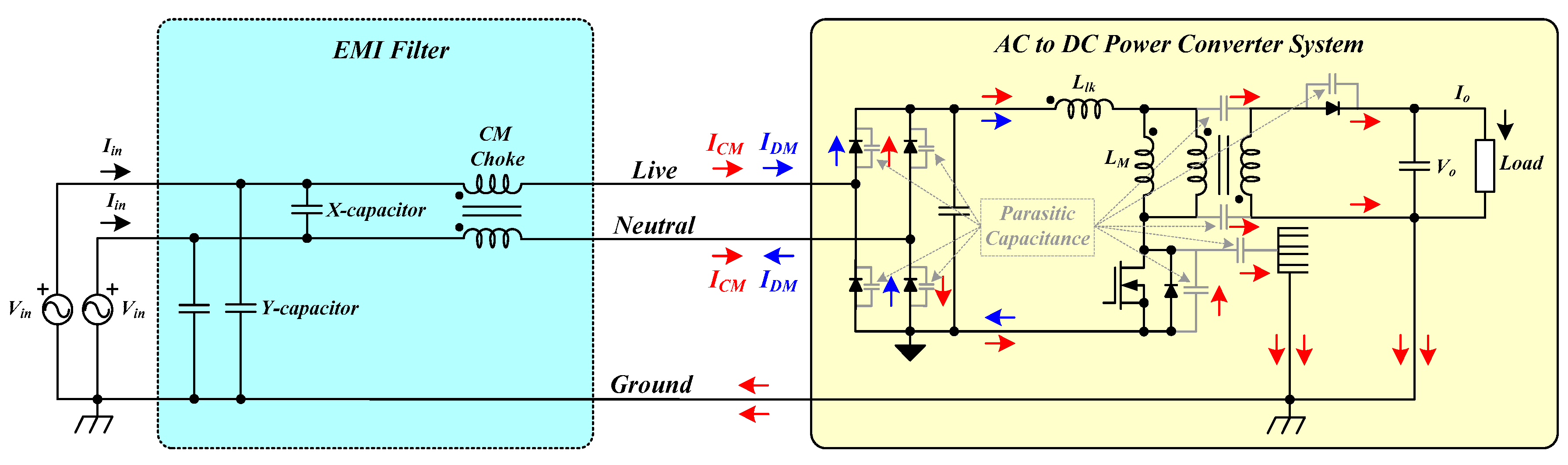
Figure 2.
CM and DM noise modeling of a conventional CM choke: (a) CM noise modeling; (b) DM noise modeling.
Figure 2.
CM and DM noise modeling of a conventional CM choke: (a) CM noise modeling; (b) DM noise modeling.
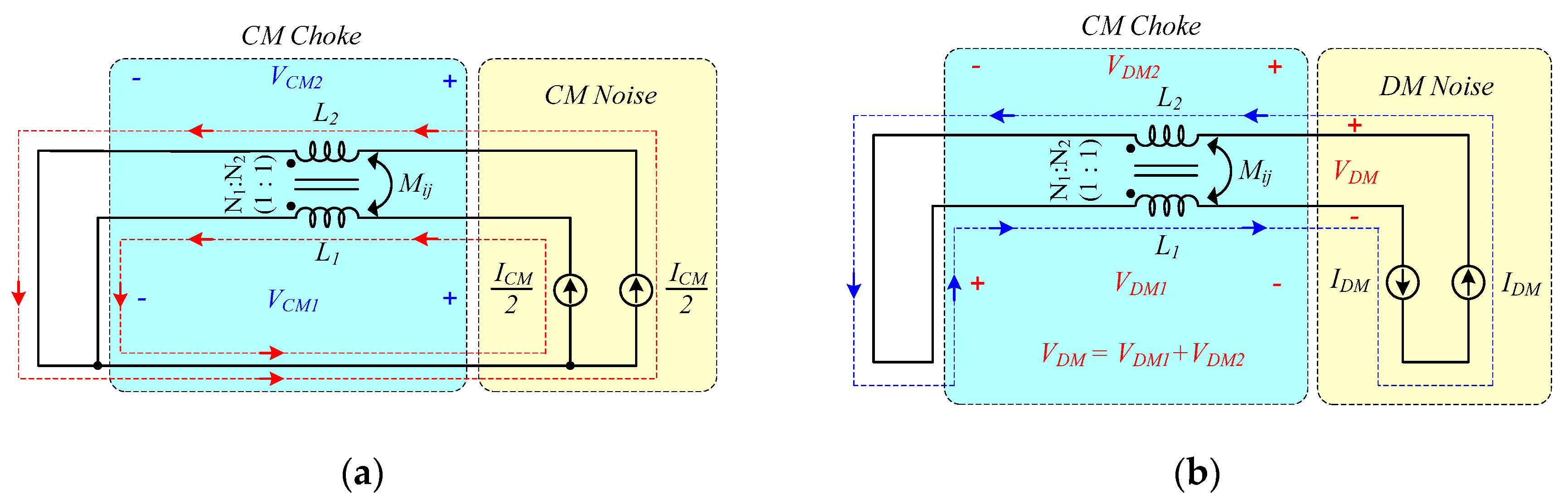
Figure 3.
CM and DM noise current flows of a conventional CM choke considering the magnetizing inductance () and the leakage inductance (): (a) CM noise current; (b) DM noise current.
Figure 3.
CM and DM noise current flows of a conventional CM choke considering the magnetizing inductance () and the leakage inductance (): (a) CM noise current; (b) DM noise current.
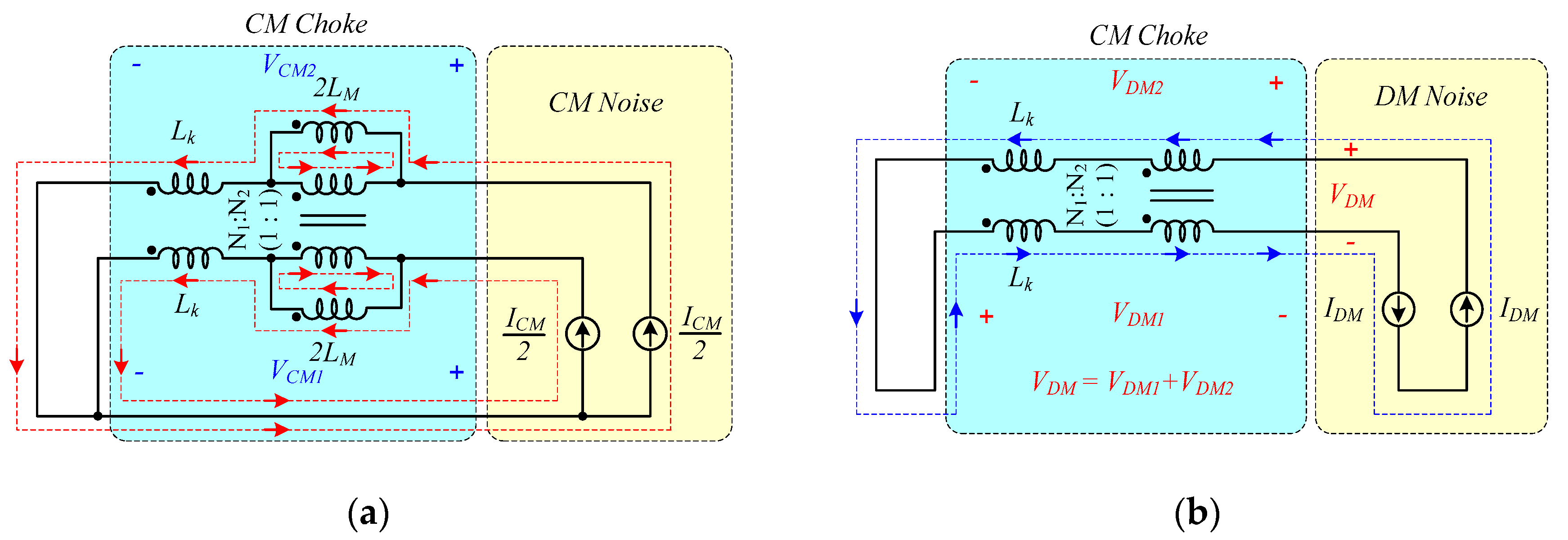
Figure 4.
Coupled and non-coupled model of the proposed CM choke at the CM noise current flow: (a) Coupled model; (b) Non-coupled model.
Figure 4.
Coupled and non-coupled model of the proposed CM choke at the CM noise current flow: (a) Coupled model; (b) Non-coupled model.
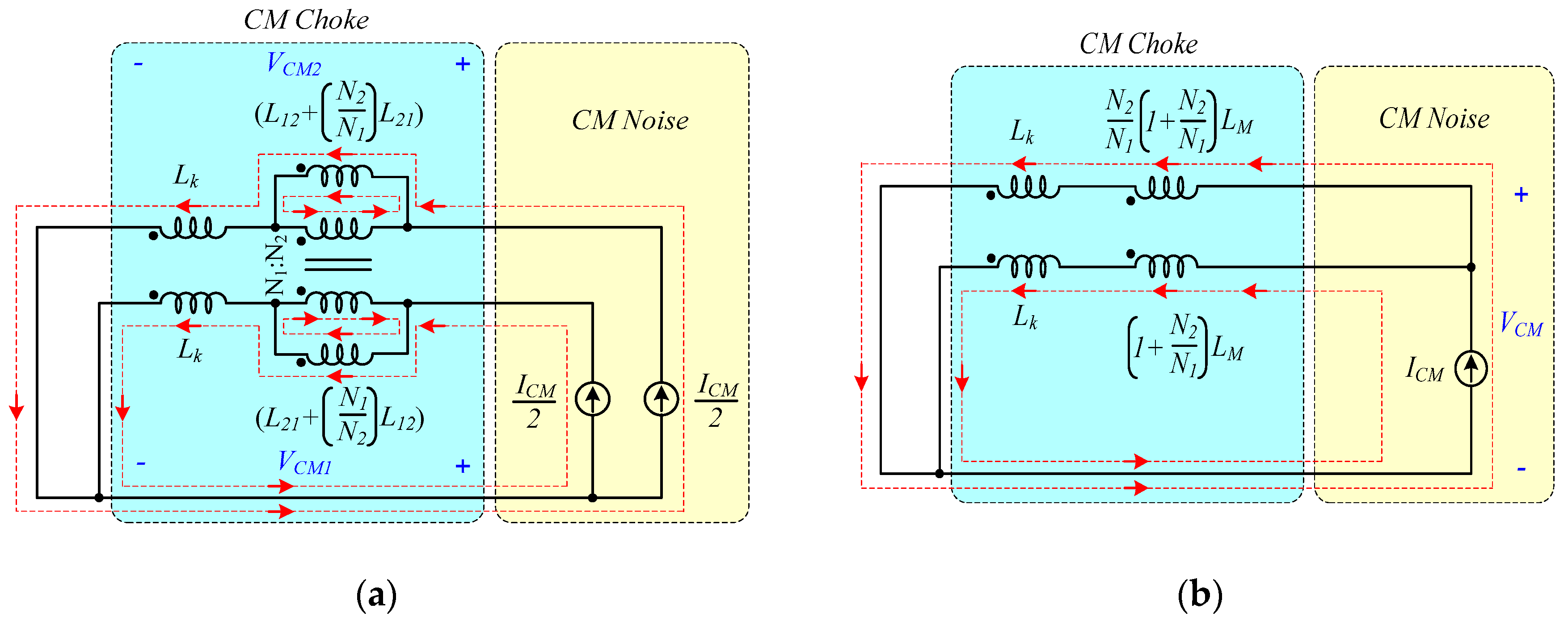
Figure 5.
Coupled and non-coupled model of the proposed CM choke at the DM noise current flow: (a) Coupled model; (b) Non-coupled model.
Figure 5.
Coupled and non-coupled model of the proposed CM choke at the DM noise current flow: (a) Coupled model; (b) Non-coupled model.
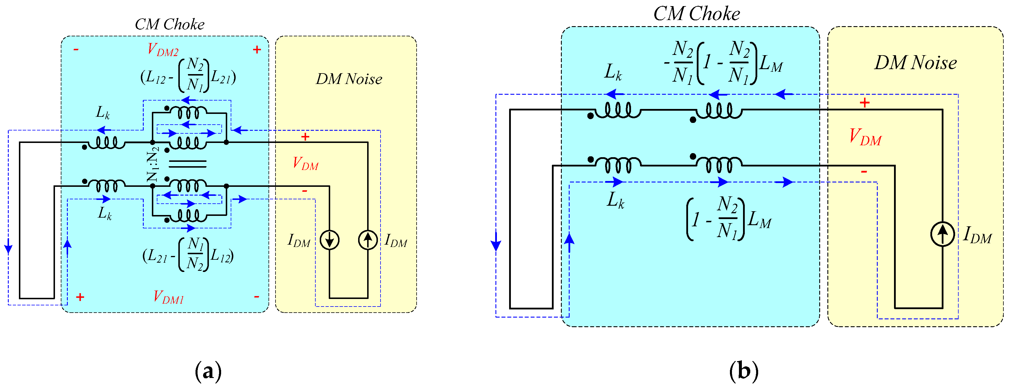
Figure 6.
CM impedances ( and ) of the conventional and proposed CM chokes calculated using PSIM simulation tool: (a) PSIM simulation circuit of and ; (b) CM impedance characteristics of and .
Figure 6.
CM impedances ( and ) of the conventional and proposed CM chokes calculated using PSIM simulation tool: (a) PSIM simulation circuit of and ; (b) CM impedance characteristics of and .
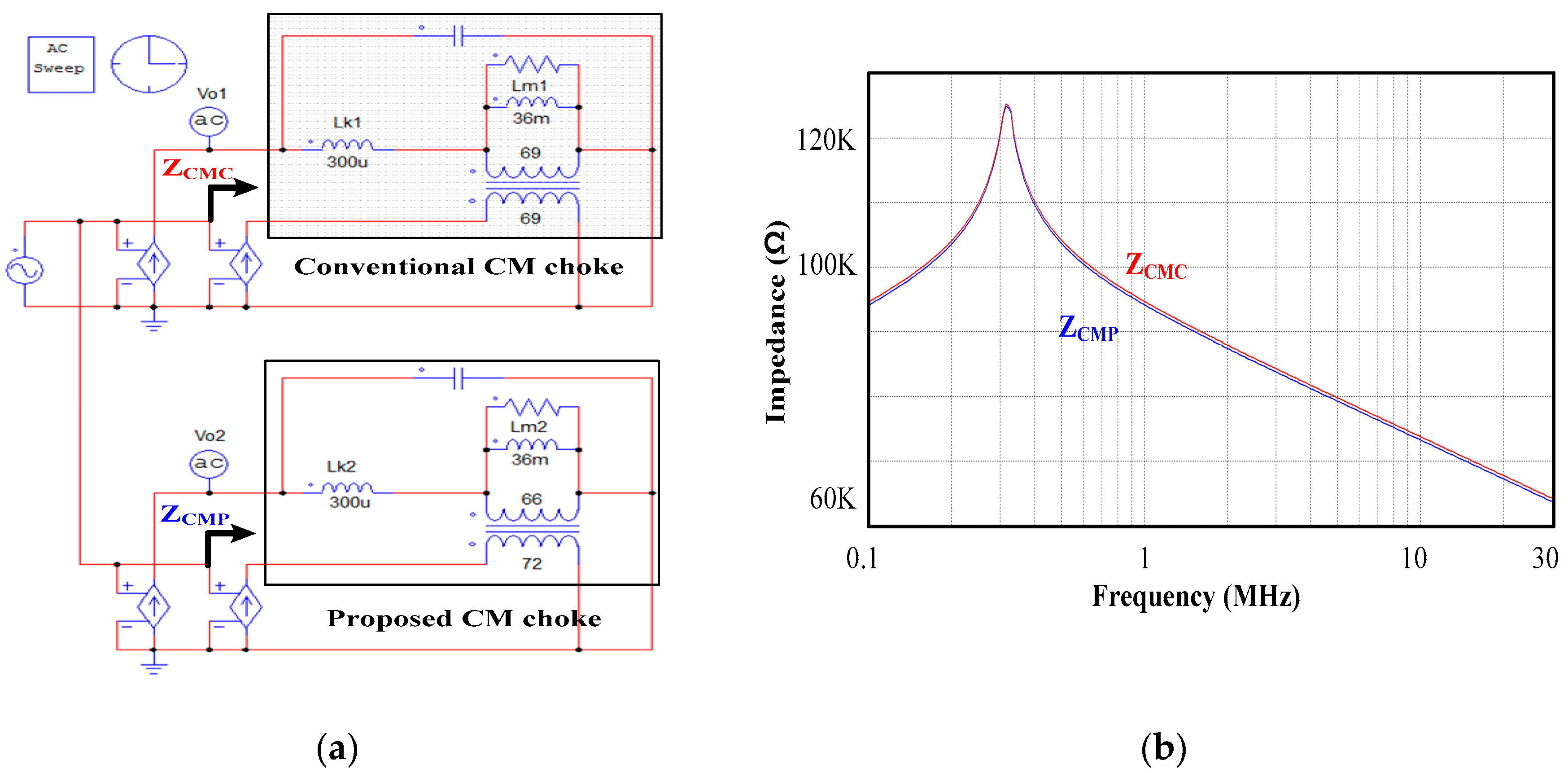
Figure 7.
DM impedances ( and ) of the conventional and proposed CM chokes calculated using PSIM simulation tool: (a) PSIM simulation circuit of and ; (b) CM impedance characteristics of and .
Figure 7.
DM impedances ( and ) of the conventional and proposed CM chokes calculated using PSIM simulation tool: (a) PSIM simulation circuit of and ; (b) CM impedance characteristics of and .
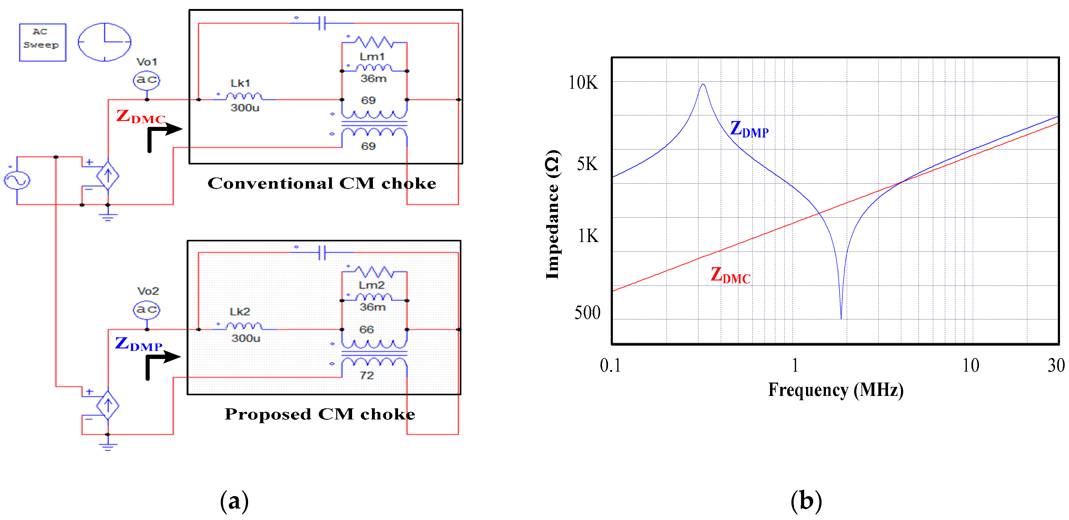
Figure 8.
A typical EMI filter configuration with its components and AC to DC Power Converter system (EMI source).
Figure 8.
A typical EMI filter configuration with its components and AC to DC Power Converter system (EMI source).
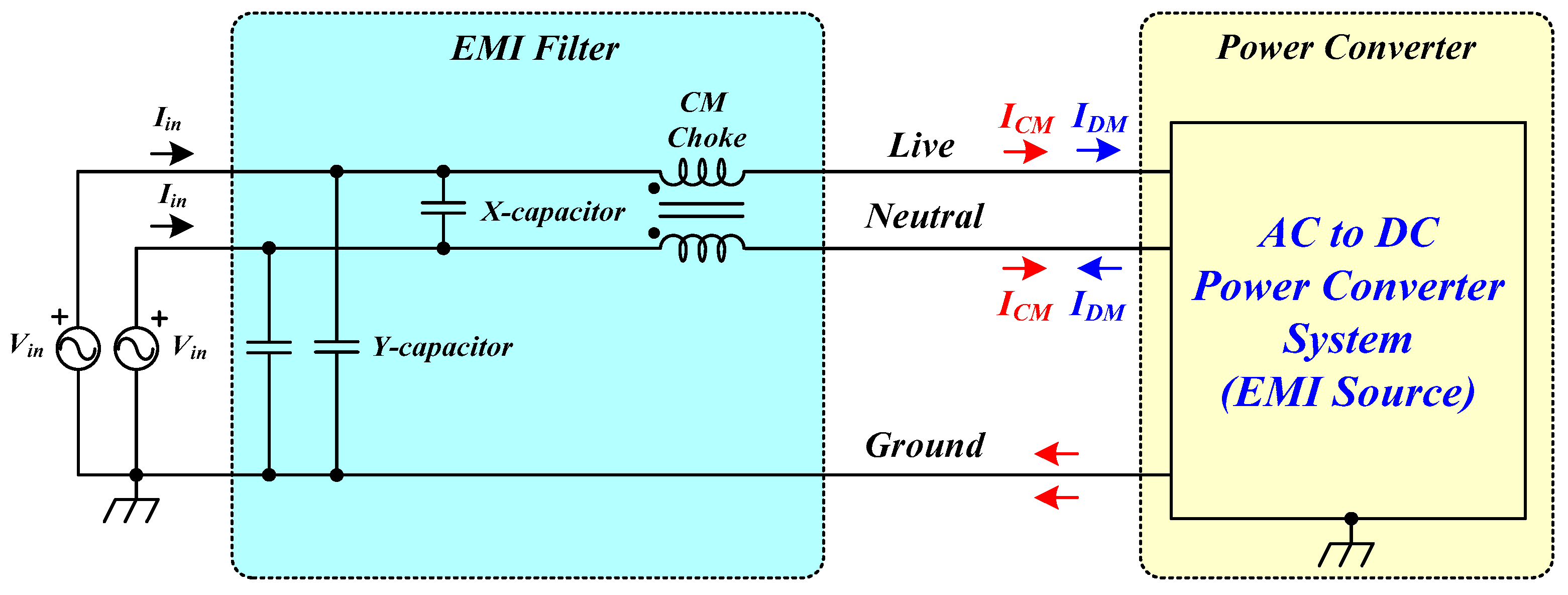
Figure 9.
Design flow chart of the proposed CM choke with asymmetrical winding.
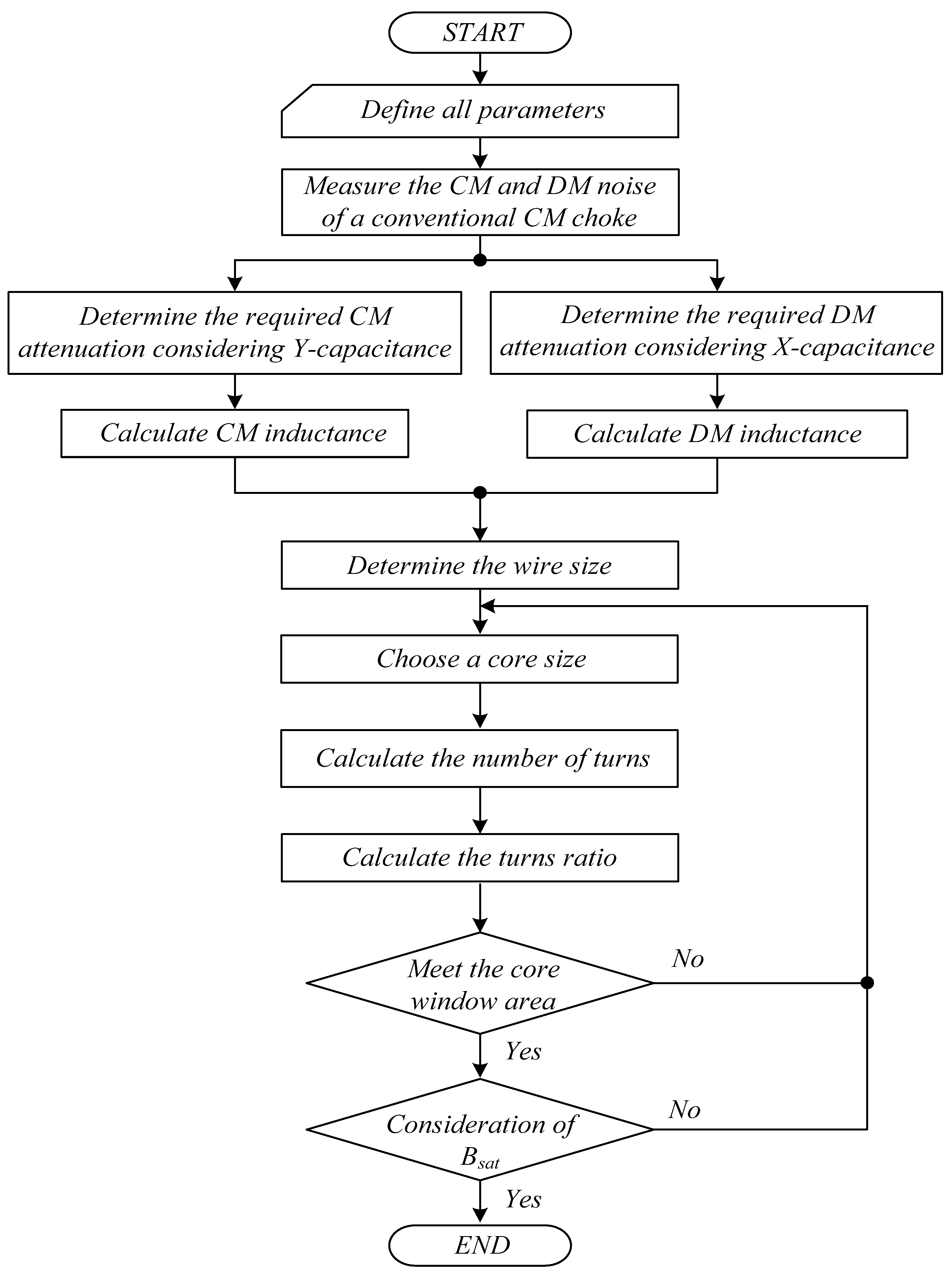
Figure 10.
The 45W Flyback DC to DC Converter implemented in an AC to DC Power Converter system.
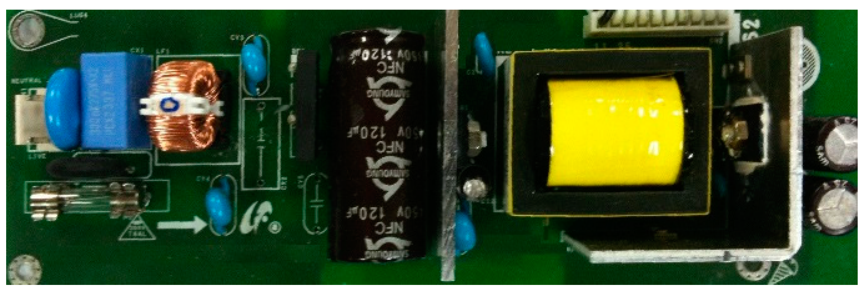
Figure 11.
Test setup of conducted EMI measurement for the proposed EMI filter in a practical AC to DC Power Converter system.
Figure 11.
Test setup of conducted EMI measurement for the proposed EMI filter in a practical AC to DC Power Converter system.
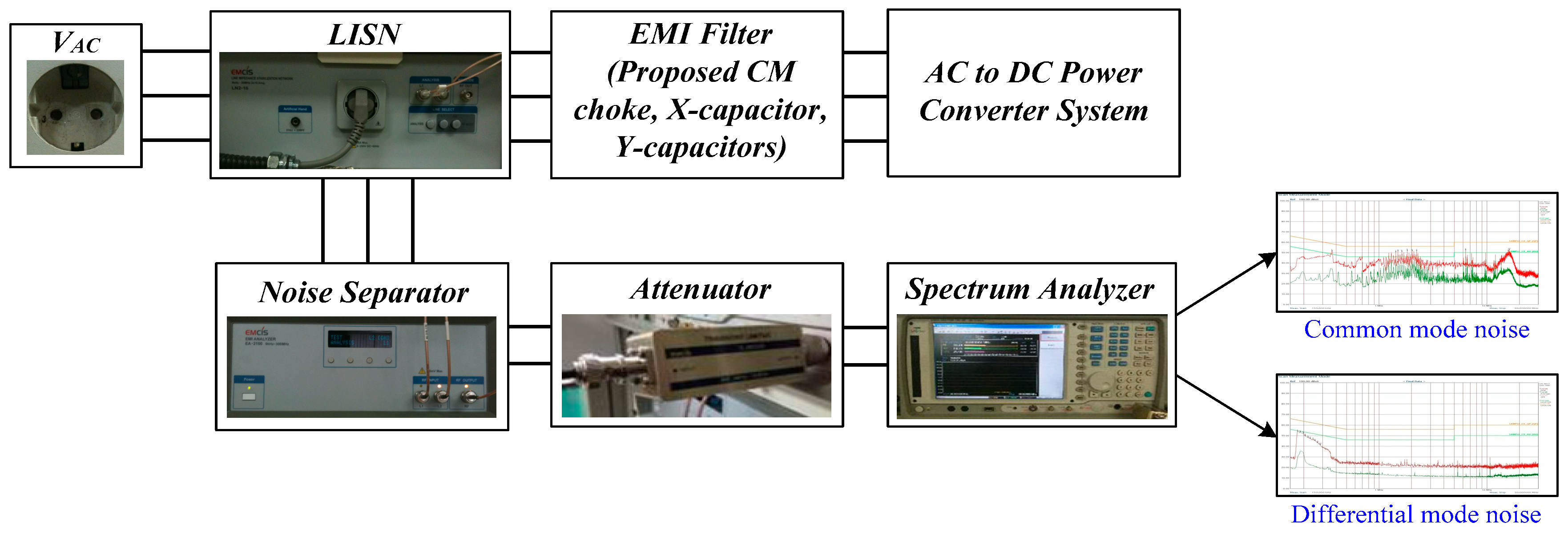
Figure 12.
Conducted EMI measurement results of a conventional CM choke: (a) Total noise of a conventional CM choke; (b) DM noise of a conventional CM choke; (c) CM noise of a conventional CM choke.
Figure 12.
Conducted EMI measurement results of a conventional CM choke: (a) Total noise of a conventional CM choke; (b) DM noise of a conventional CM choke; (c) CM noise of a conventional CM choke.

Figure 13.
Conducted EMI measurement results of the proposed CM choke with asymmetrical winding: (a) Total noise of the proposed CM choke; (b) DM noise of the proposed CM choke; (c) CM noise of the proposed CM choke.
Figure 13.
Conducted EMI measurement results of the proposed CM choke with asymmetrical winding: (a) Total noise of the proposed CM choke; (b) DM noise of the proposed CM choke; (c) CM noise of the proposed CM choke.

Disclaimer/Publisher’s Note: The statements, opinions and data contained in all publications are solely those of the individual author(s) and contributor(s) and not of MDPI and/or the editor(s). MDPI and/or the editor(s) disclaim responsibility for any injury to people or property resulting from any ideas, methods, instructions or products referred to in the content. |
© 2025 by the authors. Licensee MDPI, Basel, Switzerland. This article is an open access article distributed under the terms and conditions of the Creative Commons Attribution (CC BY) license (http://creativecommons.org/licenses/by/4.0/).
Copyright: This open access article is published under a Creative Commons CC BY 4.0 license, which permit the free download, distribution, and reuse, provided that the author and preprint are cited in any reuse.


