
Submitted:
30 September 2024
Posted:
03 October 2024
You are already at the latest version
Abstract
Current paper is aiming to show the obtained results in manufacturing and characterization of graphite-based and metal composite materials suitable to be used in high voltage application of automotive field. Thus, 4 types of materials have been processed and tested in order to assess their suitability to be used as current collector material for trolleybus. The novelty of this work is the new innovative technological process for obtaining the carbon/metal composite material used in the manufacture of sliding contacts for electrical current collector heads, as well as the character-istics obtained for this material. All 4 obtained materials have been characterized from structural (by optical microscopy), mechanical (density, electrical resistivity, hardness) and functional point of view (wear after 1000 working hours, electric discharge and electric load) and it was determined that the material which uses chemically copper covered graphite is the most suitable of them and has been chosen to be further developed by the end beneficiary.
Keywords:
graphite
; carbon composite
; high voltage
; carbon/metal
1. Introduction
Actions to combat climate change and its impacts are urgent for all countries. The transport sector, accounting for around one-fifth of global CO2 emissions, remains a focus for decarbonization. Despite the COVID-19 pandemic causing a significant decline in global emissions, the transport sector still produced nearly seven gigatons of carbon emissions in 2020. With economic recovery, transport demand is expected to rise, potentially increasing emissions if no interventions are taken [1].
Prioritizing public transport over private vehicles is critical for decarbonizing transport. Investing in high-quality, low-emission public transport improves equity by providing accessibility, especially for those who cannot afford private vehicles, and positively impacts safety. Public transport users have the lowest per capita emissions among motorized modes but suffer higher air pollution levels. Electrifying public transport, particularly in developing countries, is a priority [1].
In the US and Canada, the role of public transportation in sustainability and equity is gaining attention, with the electrification of buses being key to achieving energy transformation and equity goals [2]. The EU is also making significant progress, with the Netherlands leading in electric bus adoption and other countries like Luxembourg, Sweden, and Germany following suit under the European Green Deal, which aims to reduce net greenhouse gas emissions by at least 55% by 2030 [3].
Electrified public transport promotes energy equity, addressing environmental justice concerns in marginalized communities affected by air pollution. Deploying electric buses in these areas provides cleaner and healthier transportation options [2]. Despite impressive growth in the electrification of public transport in the EU and US over the last decade, more work is needed to transition fully from diesel-powered buses and rail networks to electric alternatives [3].
Successful implementations in cities like Amsterdam, London, Barcelona, Glasgow, and New York highlight the environmental and societal benefits of this transition. Continued global and national commitments to sustainability, infrastructure investment, and collaborative efforts are laying the foundation for a cleaner, greener future in urban transport [3].
At the early stages of electrification (2009-2013), electric vehicles technologies were not widely tested, and technical specifications varied among manufacturers. Public transport operators gained critical understanding from small-scale pilots, learning to specify vehicle and charging needs to fit their operational requirements [1].
European capitals have extensive bus and tram networks, with frequent service throughout the day and night [4]. Trolleybuses, drawing power from dual overhead wires, are a key part of this infrastructure. Early trolley shoes made from cast iron were not ideal due to abrasiveness, leading to the development of carbon/metal composites, which offer similar mechanical and electrical properties to copper but with improved mechanical properties [4,5].
On the other hand, aviation is one of the biggest pollutants today which represents the 11.6% of the total transport emissions, being a serious threat due to the proximity of the vehicles to the ozone layer. To tackle this problem, several studies are being carried out in various topics such new aircraft architectures, lighter materials, new clean fuels and electrification of major systems, including propulsion. The adoption of electric propulsion in the regional aircraft would entail significant advantages in several areas. The most transcendent benefit is the reduction of nitrogen oxides (NOx) and carbon (CO, CO2) emissions due to the independency of fuels. Along with it, the noise produced by the airplane’s turbofans will be significantly minimized [6].
Electric motors in aerospace are not new. The Airbus A380 was the first commercial aircraft to apply them across multiple onboard systems and had four variable frequency electrical generators each delivering 150kVA. Today the Boeing 787 is one of the most electric airliners, with 1.5MW of onboard power and a bleed less environmental control architecture – both provided by Collins Aerospace.
The most novel aspect of increasing the use of motors in aerospace applications lies in evolving them into a primary propulsive power source [7].
The core of the motor and the electronics were developed few years ago, and since then it has been all about proving the development, working with the regulator and proving the compliance. The next stage will be writing the test plans and getting them approved. At the moment, nothing is certified for a passenger commercial aircraft [8].
Carbon/metal composites are used in various industrial fields, including high-voltage capacitors [9], and offer advantages like lightweight, corrosion resistance, and design flexibility in high-voltage applications [10]. In the automotive and aviation industries, these composites provide superior strength and hardness, are economical, and can be heat-treated for various applications [11,12].
The experiments conducted in this research aimed at the technological processing of electro-graphitic material to obtain a carbon/metal composite material that could be used as a current collector material for high current electric engines. The characteristics of the materials need to closely match the specifications required for a semi-finished product necessary for manufacturing finished products used in the operation of traction motors, especially those used in equipping public transport vehicles.
The novelty of this work is the presentation of the new innovative technological process for obtaining the carbon/metal composite material used in the manufacture of sliding contacts for current collector heads, as well as the characteristics obtained for this material.
2. Materials and Methods
All the chemicals and reactants were produced by VWR Chemicals and provided by Laboratorium SRL, Bucharest, Romania and have lab-use purity.
Natural graphite and flake were produced and provided by ICSI Ramnicu Valcea-Roamnia and has the following characteristics:
| Granulated Natural graphite |
Flake graphite | |
| Characteristic | Value | |
| Real density (kg/m3) | 2146 | 2203 |
| Ash (A, %) | 0.82 | 0.81 |
Coal tar pitch was produced and provided by Donasid Calarasi-Romania having the following characteristics:
| Characteristic | Value |
| Real density (kg/m3) | 1206 |
| Humidity (W, %) | 0.11 |
| Ash (A, %) | 0.43 |
| Benzene insoluble material (BI, %) | 16.1 |
| Quinoline insoluble material (QI, %) | 6.59 |
| ηpitch (%) | 58.6 |
Within this chapter, the development of composite materials for sliding contacts is described. Four types of materials have been developed for testing by using different raw materials and different techniques and an assessment was made in order to determine which of those four materials is more suitable for the application. Thus, option 1 which has 2 variants includes Pitch as binder but uses two types of graphite as “lubricant”: granulated graphite and flakes. Option 2 was using a phenol-formaldehyde resin (commercially known as Novolac) as binder and granulated graphite as “lubricant”. Finally, option 3 is using Novolac as binder but graphite which was chemically coated with copper.
2.1. Option 1: Composite Obtained by Mechanical Mixing of Graphite and Copper Powders with Carbon Binder (Coal tar Pitch)
In this option, a composite was developed in which the bond between the carbon particles and the metallic particles is achieved through a carbon binder – coal tar pitch.
The raw materials used are shown in Table 1.
Figure 1 is showing the flow sheet for obtaining the composites that are using coal tar pitch as binder and granulated raw materials: graphite (2 types: granulated and flake), Sn and MoS2.
Thus, the 4 raw materials have been put together and homogenized for 3 hours in an industrial mixer (WP-M200 produced by Guangzhou Western Packing Co, China). After that, the heater of the mixer was turned on at 100˚C and the mixing process continued for 1 hour. The aim was to temper and heat the powders. The next step consisted of adding the coal tar pitch (also a powder) and rising the mixer temperature at 160˚C. The mixing was continued for another 2 hours in order to ensure a homogenous coverage of the initial raw materials with a layer of pitch (which has turned into liquid at 160˚C).
The obtained material was removed from the mixer and let to cool overnight.
When the material reached room temperature was milled in until the grain dimension was <125µm. The mill used was produced by TechnoMS, Iasi, Romania and has a 7,5-kW electric motor and is able to mill up to 1500 kg/h.
After milling, the material was homogenized once again in the mixer and them pressed at 2 tf/cm2 by using an industrial press PrHyH_I120_017, provided by Emanuel SRL, Bologna, Italy.
The pressed blocks have been after that treated at 900˚C in an Nabertherm furnace, in the presence of Argon and by using the following thermal treatment diagram:
2.2. Option 2 (CNNH): In This Option, an Isotropic Structure Composite Was Developed in Which the Bond between the Carbon Particles and the Metallic Particles Is Achieved through an Organic Binder – Novolac. To Achieve Better Compactness and Structural Uniformity, the Powder Mixture Was Coated With the Binder
The raw materials used are shown in Table 2.
Figure 3 is showing the flow sheet for processing Novolac based composites (CNNH). For cross-linking the binder, 5% HMTA (hexamethylenetetramine) was added relative to the Novolac. The process is similar to the previously presented one but in addition a solution of 50% Novolac was prepared and added to the mixture. This solution was prepared by adding Novolac and 5% HMTA in a 3D Shaker Mixer & Mill EQ-SYH-5 produced by MTI Corp, California USA and provided by MatTek Lab, Istanbul, Turkey and mixing it for 1 hour. After that Ethilic alcohol was added in order to obtain Novolac solution 50%.
The steps taken to obtain this kind of material were similar to the previously ones but the thermal treatment in the presence of Ar went just until 650˚C in order to avoid the destruction of the cross-links formed between Novolac and HMTA.
The thermal treatment diagram is shown in Figure 4.
2.3. Option 3 (CCN): Material Obtained from Composite Powder (Graphite Chemically Coated with Copper) with Organic Binder – Novolac
In this option, a composite was created in which the bonding of graphite particles with copper is physical in nature. The addition of the binder aimed to densify and increase hardness without the metal forming a continuous network.
Globally, research is ongoing regarding the chemical deposition of metals on graphite to obtain advanced composites. Such a study was presented at the conference [10].
The method used for chemically plating graphite with copper involves a series of steps, which are presented below (Figure 5).
Table 3 is showing the raw materials used for obtaining CCN material.
Basic reduction reactions of Cu are shown in equations 1 and 2 but the chemicals and solutions involved in this step are subject to a patent submitted by the end user of the material.
resulting metallic Cu (Cu0) which bonds with the graphite. The bonding is realized by the π electrons of graphite which allows the forming of the metallic layer on the surface.
2Cu2 reduction 2Cu+
2Cu+ Cu2+ + Cu0,
After the metal plated graphite powder is obtained, it is used as raw material for composite manufacturing as shown in Figure 6:
3. Results and Discussions
All the obtained composite materials have been characterized from structural and mechanical point of view and the results are shown as follows:
From mechanical point of view, the following characteristics have been determined: initial density (before thermal treatment), final density (after thermal treatment), electrical resistivity, hardness, mechanical strength and the results are shown in Table 1.
The density of the material was calculated after the measurements of their dimensions and weighing them on an electronic balance provided by Kern, model ALT 220-4NM.
Electrical resistivity was measured by using M9115 Electrical Resistivity System provided by Grace Instruments.
HB hardness was measured by using EMCO-Test M4C025G3M apparatus, provided by Bruker Corp., Massachusetts, USA.
As it can be assessed from Table 4, the materials’ density increases after the thermal treatment and GCA shows the highest value. Also, CCN shows the highest value for mechanical strength and the lowest value for electrical resistivity, meaning that CCN material is the most resistant one, the denser and has the highest electrical conductivity, allowing thus electric current to pass more rapidly leading to a lower heating of the material.
From structural point of view, all 4 obtained materials have been analyzed under optical microscope at 50x. The device was provided by AXIO and is fitted with a Lumix photo camera.
As it can be observed from Figure 7, all the materials show high homogenization and structural integrity. Moreover, after the thermal treatment there are no visible pores within the structure of the material.
Also, functional characterization has been made within the lab and the following characteristics have been determined: electric discharge both at working and maximum imposed current, friction coefficient and mechanical wear after 1000 hours of work. The setup, as it can be seen in Figure 6 consisted of an array of equipment measuring the electrical parameters and also an equipment ensuring the equivalent force of the real equipment fitted on the trolleybus. Also, a copper wire similar to the ones used for trolleybus lines was continuously moved for 1000 hours while the above-mentioned apparatus was applying the force. The schematics of the equipment is shown in Figure 8 but the real characteristics are also subject to a patent application held by the end-user of the materials.
Table 5 is showing the electric discharge and the applied electric load of each of the samples.
As it can be assessed form Table 6, CNNH material shows the lowest electric discharge while graphite-based materials are showing increased values.
Table 6 is showing the friction coefficient and mechanical wear after 1000 hours of work. The materials have been tested in controlled conditions by using a brand-new trolleybus wire and the speed of the trolleybus was kept constant at 60 km/h.
As it can be observed the friction coefficient ant mechanical wear after 1000 working hours and, as expected graphite-based materials, CNS and CFS shows the lower friction coefficient but the highest wear. This is correlated to their lower mechanical strength. In the meantime, CNNH is showing the lowest mechanical wear even though its friction coefficient is several times higher than graphite-based materials.
Other researches have been focused on alloying the copper either with Al-Sn/Si and/or Pb and after that inserting the alloy within the material of the sliding contact [11].
Even though, the obtained materials have shown similar hardness as the one studied within this paper, the testing of the materials have been made only for 27 km and no discharge testing have been made.
Figure 8.
Comparison with other studied materials.
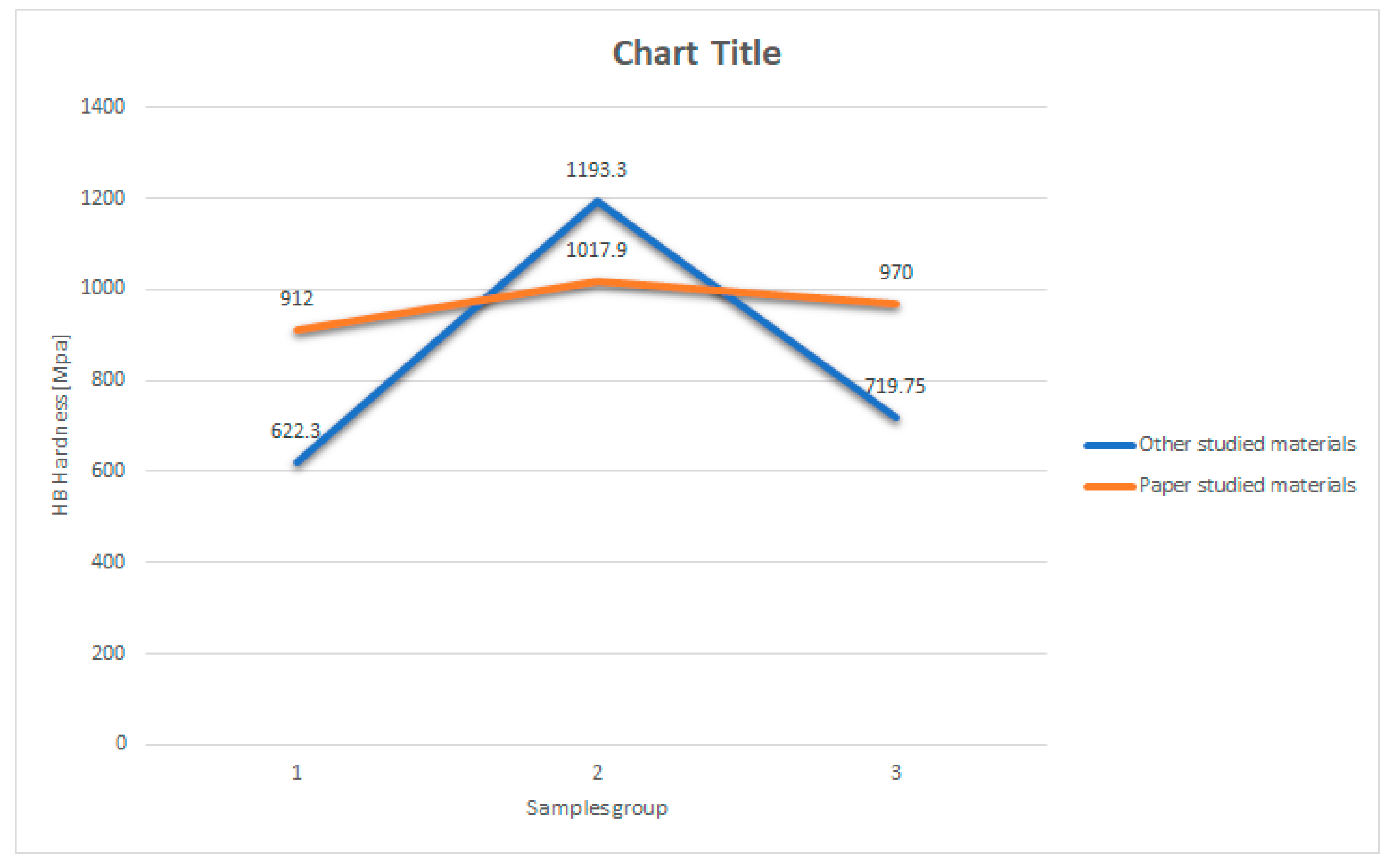
Figure 8 is showing a comparison of the HB wickers hardness of the materials studies here and the ones studied by other papers.
As it can be observed from Figure 8, the HB hardness properties of the materials obtained within this paper are more uniform varying from 912 to 1017 MPa, while the ones obtained by other papers are too apart varying from 622 to 1193 MPa.
As mentioned, even though other studied materials show better mechanical properties, they haven’t been tested for such long distance and, as shown in paper [11], they already had mechanical wear. While the materials studied within this paper showed mechanical wear varying from 13 to 38 mm after 1000 working hours.
Moreover, currently, the sliding contacts commonly used are made of cast iron which has high mechanical and wear resistance but which during the electrical discharge forms small iron debris which, in time lead to mechanical wear of the copper wire, making it very expensive to replace. Even though the materials studied within this paper can form copper debris during an electric discharge, these debris have similar mechanical properties as the wire and does not wear it out, making them more suitable and less costly to use.
4. Conclusions
Analyzing the characteristics of the composites, it can be concluded that:
- Although they have similar hardness values, the four materials exhibit different coefficients of friction, determined under identical conditions, depending on each one's chemical composition and processing method, as follows:
- Materials with a pitch binder that also contain molybdenum disulfide as a lubricant have much lower coefficients of friction than those with a Novolac binder that contain no other lubricant besides graphite.
- The composite made of copper-plated graphite powder has the highest coefficient of friction, which can be explained by the fact that the graphite can no longer act as a lubricant due to the coating.
- From the perspective of mechano-electrical wear, it can be said that although they have similar hardness and mechanical strength, the materials wear differently depending on electrical conductivity and voltage drop, as follows:
- The copper-graphite pitch composites (CNS and CFS), which have the highest electrical resistivity and voltage drop, wear the most.
- The copper-graphite-Novolac (CNNH) composite exhibits the lowest wear, having quite high electrical resistivity but the lowest voltage drops.
- Regarding the composite based on copper-plated graphite powder, the relatively high wear is due to the fact that, despite having very low electrical resistivity, the phenomenon of copper migration from the network occurs much more easily.
- These results shown within the paper are obtained within the lab. Therefore, testing in real life conditions is needed in order to correctly assess if the developed material which shows the most promising perspectives in suitable for the end purpose of the work.
Author Contributions
Authors individual contributions “Conceptualization, RM; methodology, RM and RE.; validation RM, RE and DE; formal analysis DE.; investigation, RE; resources, RM.; data curation, RE and DE; writing—original draft preparation, RM.; writing—review and editing, RM.; All authors have read and agreed to the published version of the manuscript.
Funding
This work has received no funding.
Acknowledgments
The authors would like to acknowledge the administrative support of Romanian Research and Development Institute for Gas Turbines, COMOTI.
Conflicts of Interest
The authors declare no conflicts of interest
Abbreviations
| HMTA | hexa-methylene tetra amine |
| CNS | Composite-Natural graphite-Sn |
| CFS | Composite-Flake-Sn |
| CNNH | Composite-Natural graphite-Novolac-HMTA |
| CCN | Composite-Coated graphite-Novolac |
References
- The World Bank. Electrification of Public Transport: A Case Study of Shenzhen Bus Group; License: Creative Commons Attribution CC BY 3.0 IGO; World Bank: Washington, DC, 2021. [Google Scholar]
- Bryan Jungers, Could electrifying public transportation be the key to achieving energy equity goals? , 2008 - 2024 E Source Companies LLC, February 21, 2024.
- Heliox Energy, How have countries around the world electrified public transport? July 10, 2023.
- Available online: https://visitbucharest.today/bucharest-public-transport/ (accessed on 15 March 2024).
- Available online: https://en.wikipedia.org/wiki/Trolleybus (accessed on 5 September 2023).
- Alvarez, P.; Satrústegui, M.; Martinez-Iturralde, M. Review of High Power and High Voltage Electric Motors for Single-Aisle Regional Aircraft. IEEE Access 2022. [Google Scholar] [CrossRef]
- Roper, J. The advances in motor technology driving the development of electric aircraft. Aerospace Testing International 04. 2023.
- Armesmith, R. “Electric motors for aircraft”, E-Mobility Engineering, 2024.
- Liu, C.-F.; Liu, Y.-C.; Yi, T.-Y.; Hu, C.-C. Carbon materials for high-voltage supercapacitors. Carbon 2019, 145, 529–548. [Google Scholar] [CrossRef]
- Bhalerao, S.; Ambhore, N.; Kadam, M. Polymer Matrix Composite in High Voltage Applications: A Review. Biointerface reaesarch in applied chemistry 2022, 12, 8343–8352. [Google Scholar]
- Three D Metals, 5 Advantages High Carbon Steel Brings to the Automotive Industry, January 26, 2024.
- Achour, B.; Ouinas, D.; Touahmia, M. Boukendakdji Buckling of Hybrid Composite Carbon/Epoxy/Aluminum Plates with Cutouts. Engineering, Technology and Applied Science Research 2018, 8, 2393–2398. [Google Scholar] [CrossRef]
- Tsiskarishvili, R. Study of the process of copper plating graphite by chemical method. Proceedings of National Academy f Sciences of Belarus 2013, 39, 184–188. [Google Scholar]
- Shyrokov, V.V.; Vasylenko, Y.I.; Khlopyk OPFrenchko, M.S. Development of antifriction Aluminum-base alloys and compositions for sliding current collectors. Materials Science 2006, 42, 843–848. [Google Scholar] [CrossRef]
Figure 1.
Flow sheet for obtaining Cu/Graphite/Pitch composite material (CNS/CFS).
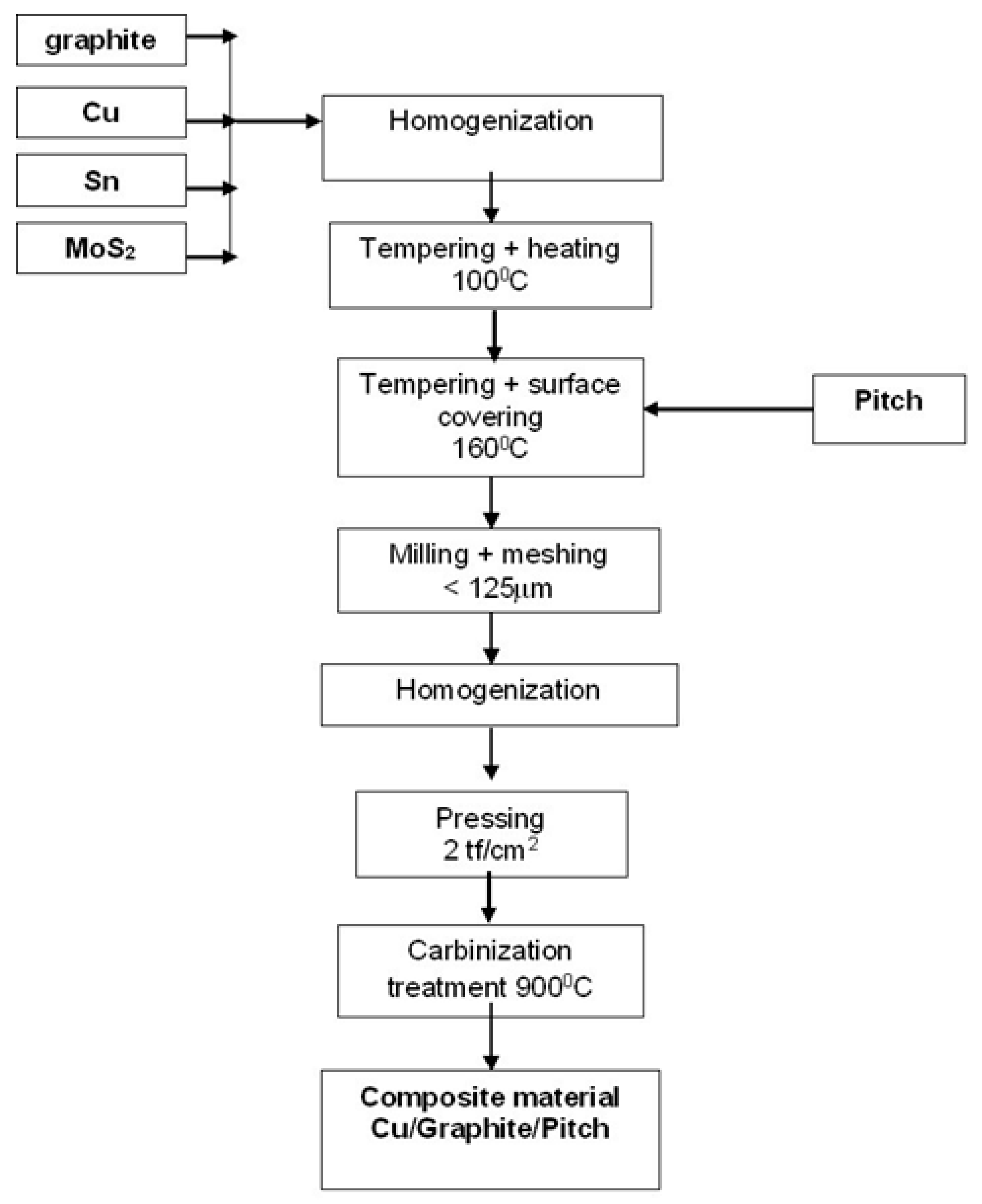
Figure 2.
Thermal treatment diagram.
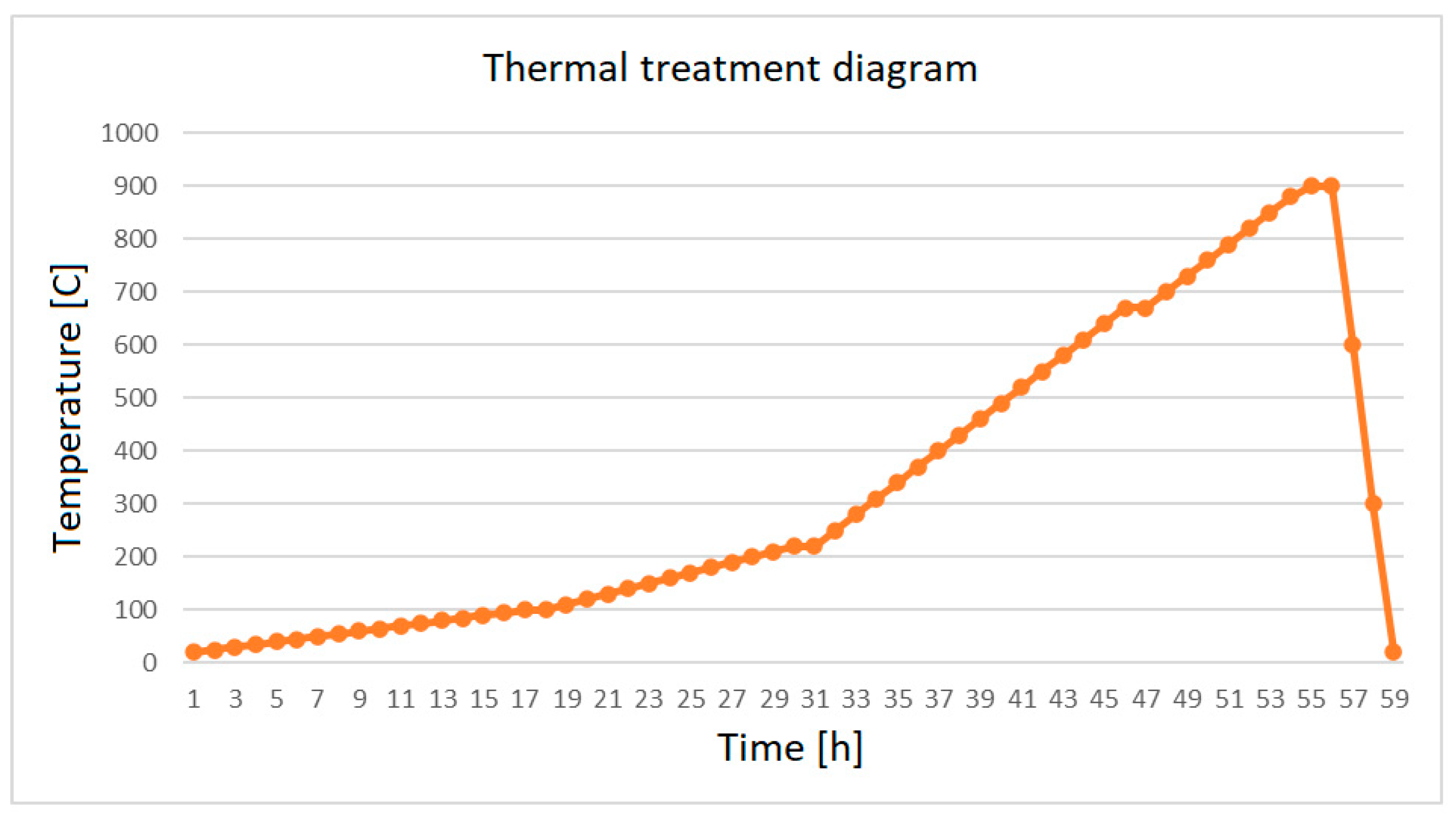
Figure 3.
Flow sheet for obtaining Cu/Novolac/Graphite composite material (CNNH).
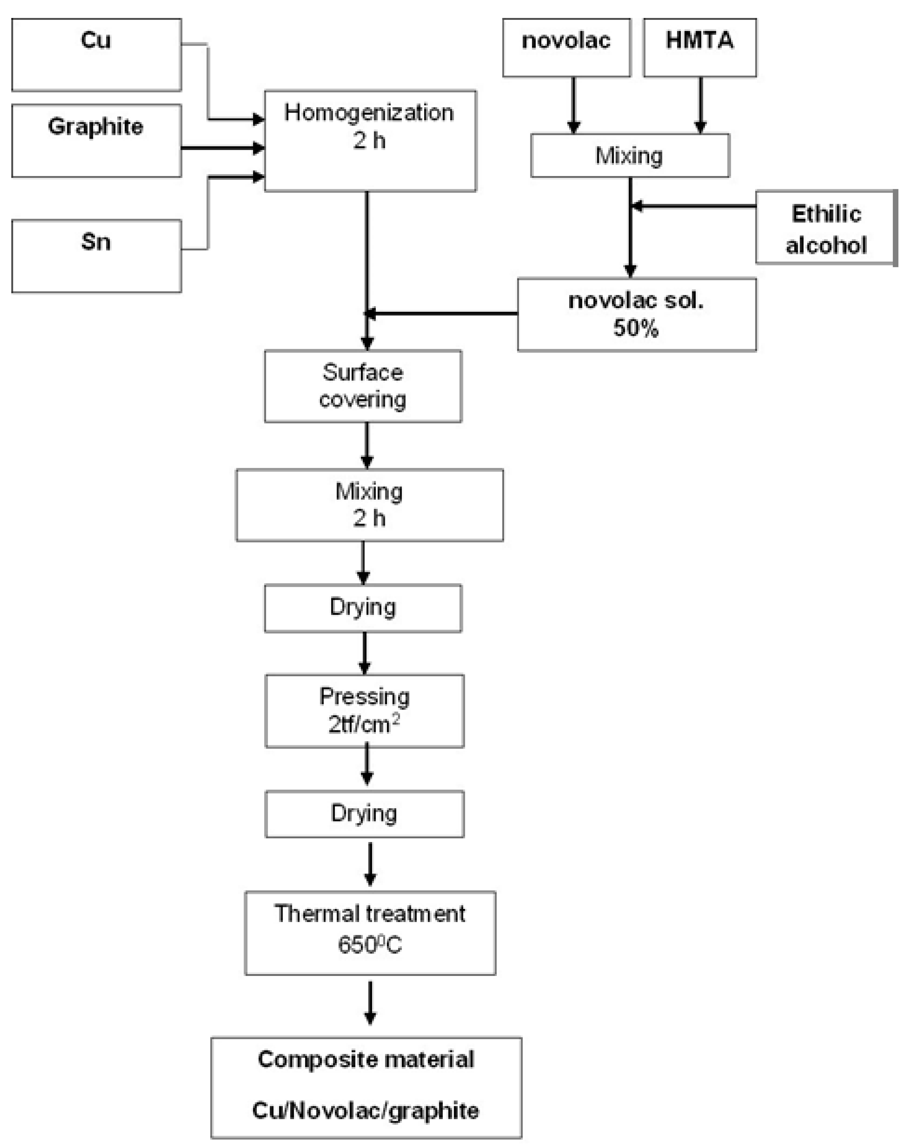
Figure 4.
Thermal treatment diagram.
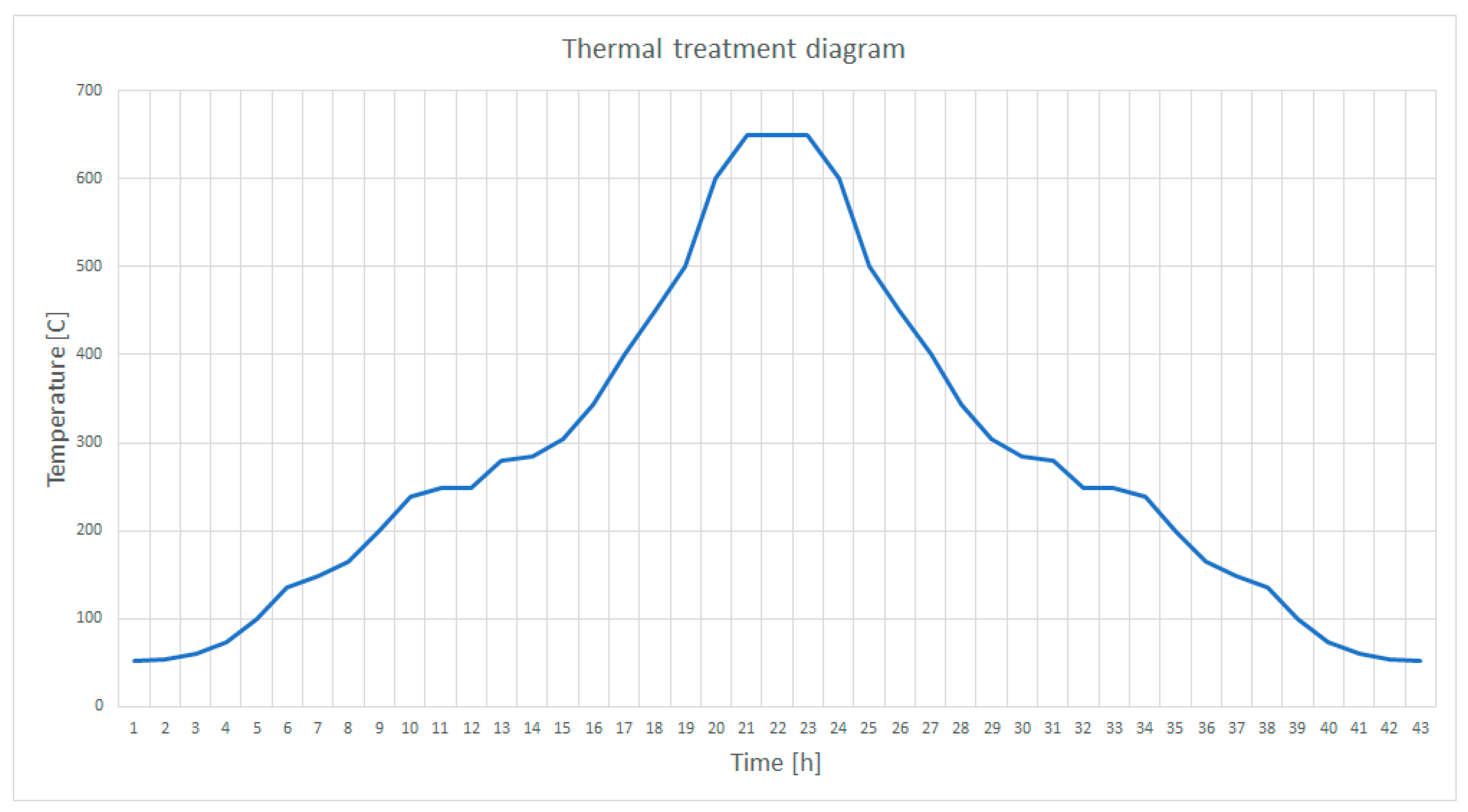
Figure 5.
Flow sheet for obtaining Cu plated graphite.
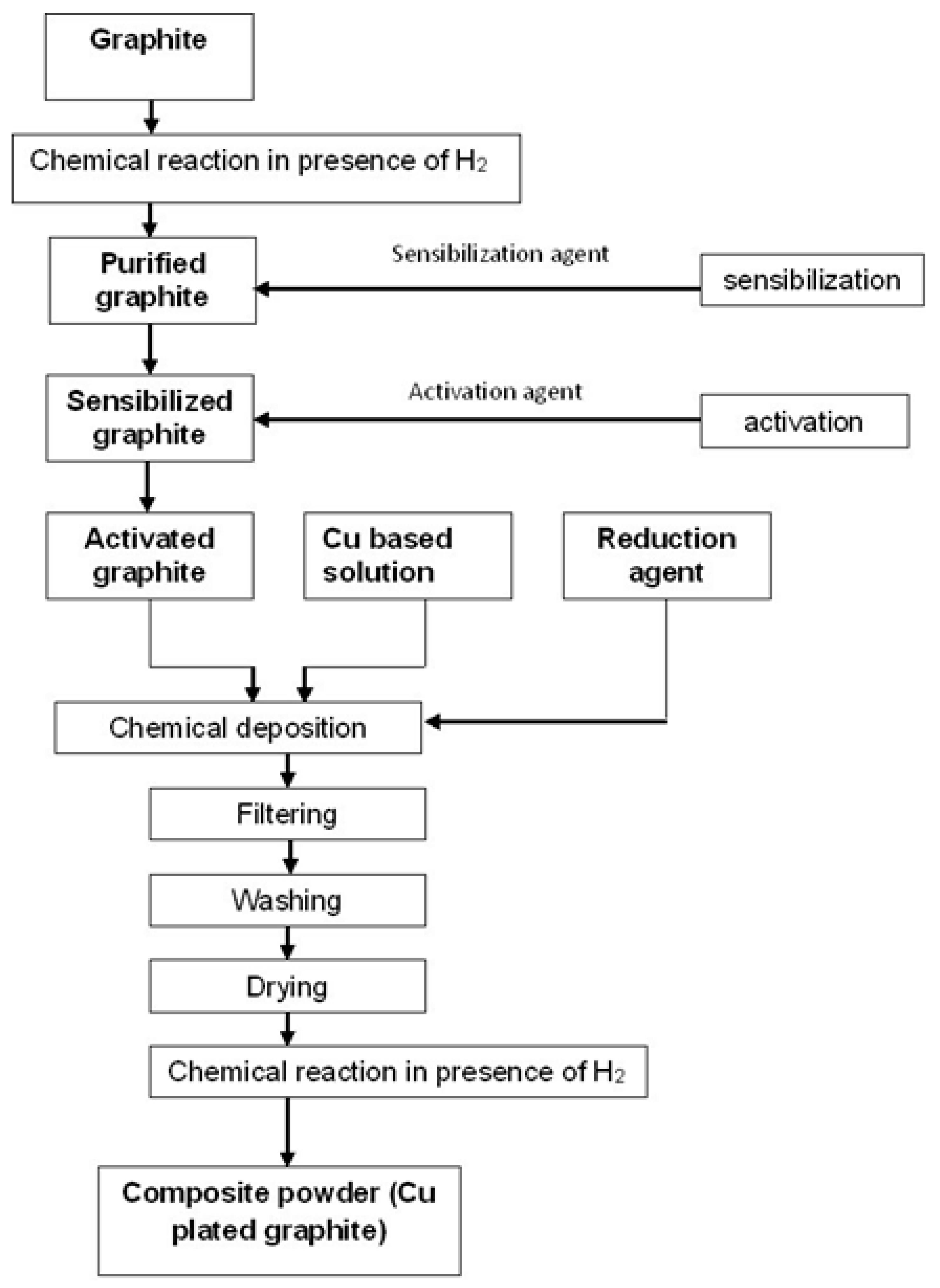
Figure 6.
Flow sheet for obtaining Cu plated graphite/Novolac composite material (CCN).
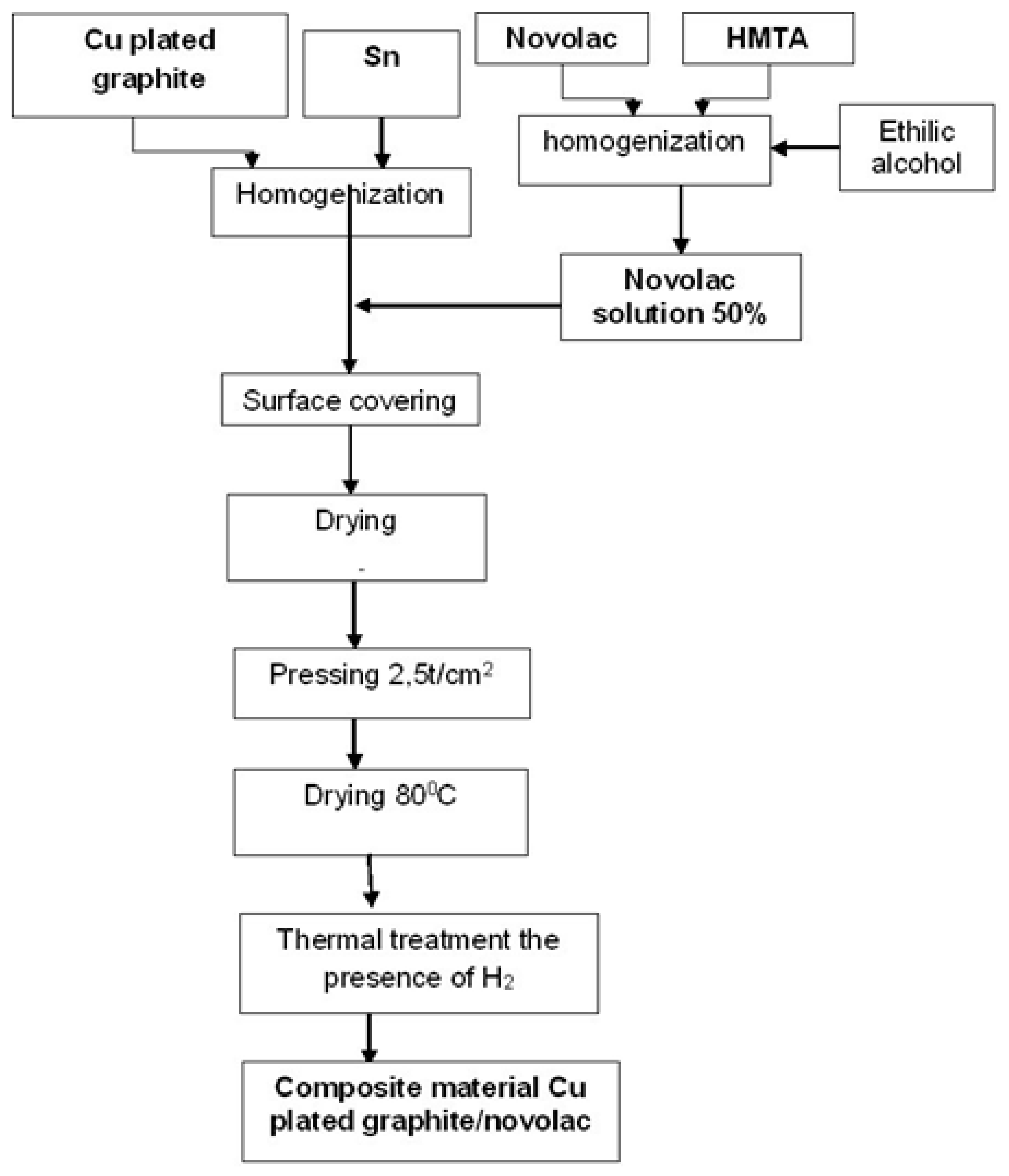
Figure 7.
Images of the obtained materials.
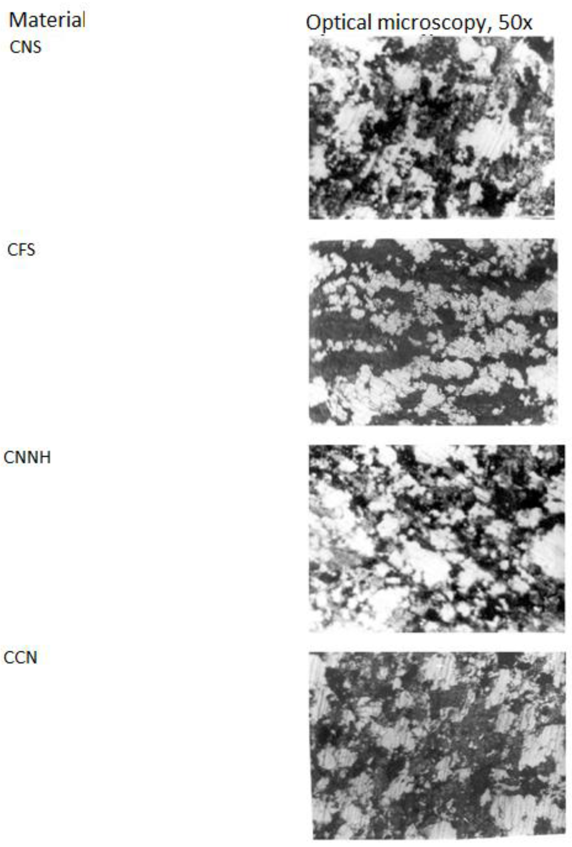
Figure 8.
Schematic of functional characterization setup.
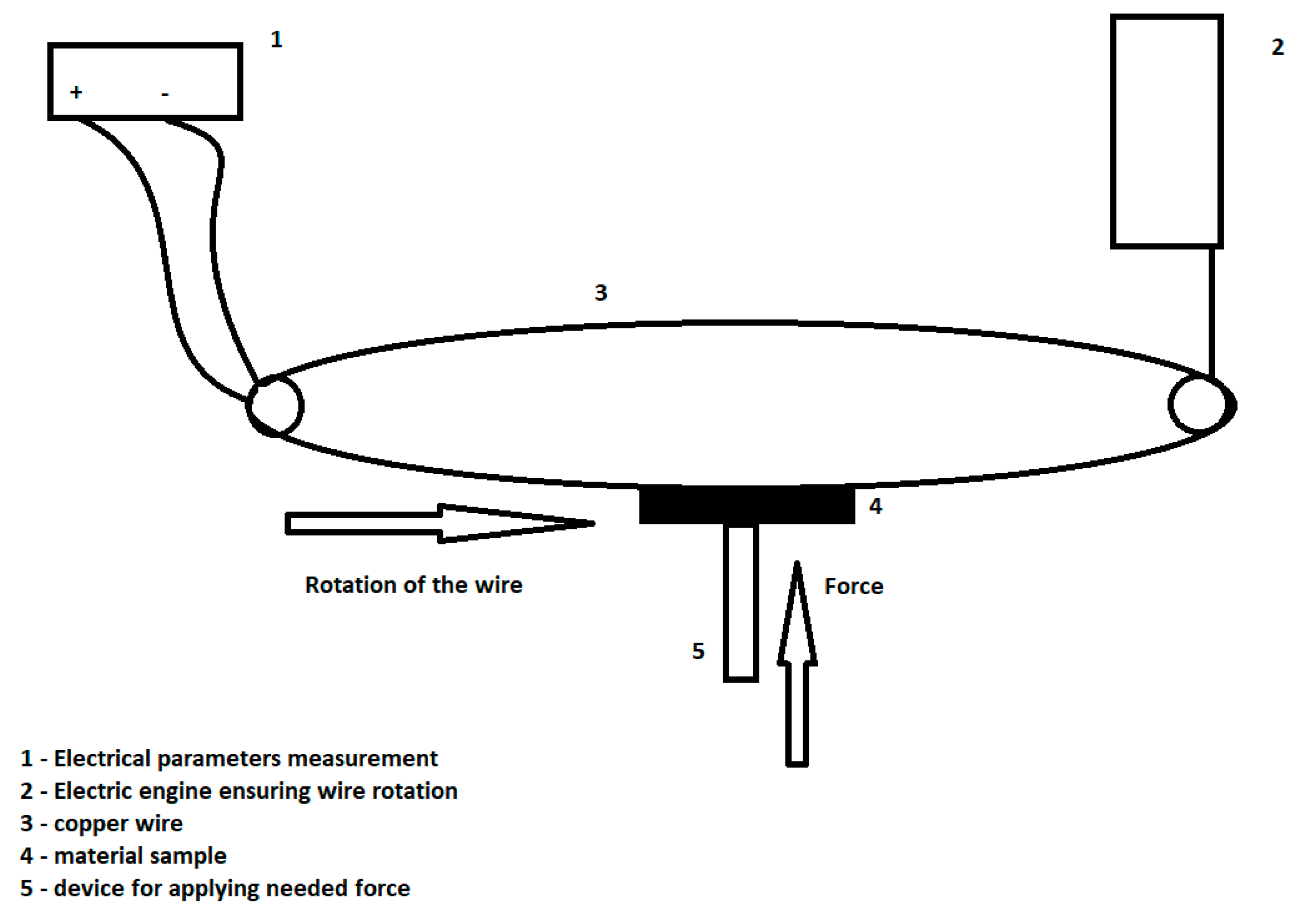

Table 1.
Raw materials quantities used for obtaining coal tar pitch-based composites.
| Material | CNS | CFS |
| Raw material | Quantity [% wt.] | Quantity [% wt.] |
| Granulated natural graphite (>100 μm) | 18 | - |
| Flake natural graphite | - | 18 |
| Electrolytic copper powder | 60 | 60 |
| Sn powder | 7 | 7 |
| Molybdenum disulfide (MoS₂) | 5 | 5 |
| Coal tar pitch | 10 | 10 |
Table 2.
Raw materials used for obtaining Novolac-HMTA based materials.
| Raw material | Quantity [% wt.] |
| Granulated natural graphite (>100 μm) | 15 |
| Electrolytic copper powder | 60 |
| Sn powder | 7 |
| Novolac (which includes 5% HMTA) | 18 |
Table 3.
Raw materials used for obtaining CCN materials.
| Raw material | Quantity [% wt.] |
| Copper plated graphite | 75 |
| Sn powder | 7 |
| Novolac (which includes 5% HMTA) | 18 |
Table 4.
Mechanical characteristics for the obtained composites.
| Material | Initial density, [g/cm3] |
Final density, [g/cm3] | Electrical resistivity, [µΩm] |
Hardness HB10/40 [kgf/mm2] | Mechanical strength, [MPa] |
| CNS | 3,4 | 3,6 | 157 | 107,6 | 32,7 |
| CFS | 3,4 | 3,6 | 151 | 100 | 30,5 |
| CNNH | 3,0 | 3,2 | 100 | 93 | 25 |
| CCN | 3,6 | 3,7 | 7,5 | 99 | 38 |
Table 5.
Electric discharge and electric load.
| Material | Electric load (min/max) J, [A/cm2] | Electric discharge 2Ue, [V] |
| CNS | 25 | 2 |
| 50 | 3,20 | |
| CFS | 25 | 3,40 |
| 50 | 5,03 | |
| CNNH | 25 | 1.2 |
| 50 | 1.93 | |
| CCN | 25 | 1.2 |
| 50 | 2.04 |
Table 6.
Friction coefficient and mechanical wear after 1000 hours of work.
| Material | Friction coefficient at 60 km/h (μ) |
Mechanical wear after 1000 working hours (mm) |
| CNS | 0,11 | 23 |
| CFS | 0,05 | 38 |
| CNNH | 0,27 | 13 |
| CCN | 0,3 | 26 |
Disclaimer/Publisher’s Note: The statements, opinions and data contained in all publications are solely those of the individual author(s) and contributor(s) and not of MDPI and/or the editor(s). MDPI and/or the editor(s) disclaim responsibility for any injury to people or property resulting from any ideas, methods, instructions or products referred to in the content. |
© 2024 by the authors. Licensee MDPI, Basel, Switzerland. This article is an open access article distributed under the terms and conditions of the Creative Commons Attribution (CC BY) license (http://creativecommons.org/licenses/by/4.0/).
Copyright: This open access article is published under a Creative Commons CC BY 4.0 license, which permit the free download, distribution, and reuse, provided that the author and preprint are cited in any reuse.


